How should the panels UI look? This is unrelated to the Principled BSDF and is instead a general UI discussion. Maybe @LukasTonne or someone else (@pablovazquez or @dfelinto) could create a UI feedback thread for panels and the ideas can be shared over there.
How the Principled BSDF should take advantage of panels. This discussion is about the Principled BSDF “v2” work and should probably take place in this thread.
Lukas Stockner liked the idea, but didn’t have strong opinions. Brecht didn’t have any strong opinions.
So I went with the order I did (the current ordering in main) because it mostly lines up with the layering inside the shader, and the node still looks visually pleasing.
There is still time for the order to be changed, so if people have strong opinions about what order they want, it can be changed.
Note: My order is backwards compared to yours. Here is my reasoning:
Users will mostly work from the top of the node downwards. So we should order the panels like that. Have the base layers of the material (Diffuse, Metal, Transmission, Subsurface) at the top of the node, and the top layers of the material at the bottom of the node (Specular, Coat, Sheen). That way as the user goes from the top of the node down to the bottom, they are layering materials on top of each other in the order they progress down the node.
Emission should sit between Specular and Coat. But I placed it at the bottom due to the “Visually pleasing” thing I mentioned earlier.
Yo, got a few question and thoughts about the subsurface scattering updates
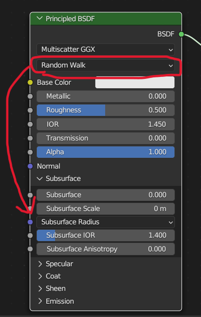
Having a Subsurface and a Subsurface Scale slider feels like both of them are doing the same thing, except they are not. From my small testing the Subsurface slider sort of “fades” between whatever subsurface you have to just a default diffuse shader, while the Subsurface Scale slider actually scales it in a more physically correct way. Is my assumption correct? Because if that’s the case I think it should be more clear somehow what slider one should use if you want a more physically correct material.
It kind of feels like the Bump node where you really shouldn’t use the Strength slider since it just “fades” between full bump and no bump which is not the right way to do it, it just looks bad no matter how you arbitrary change that slider, and unfortunately almost everyone still uses that slider because it’s labelled in such a way that people think that’s the one to use (and also since you generally have to set the Distance to very low values to have any real effect since this value is in meter (which is not really clear either)).
And about that radius, this might be nit picking, but shouldn’t the input be an RGB one since that’s what you essentially is just multiplying the scale with in there? I mean if you change individual channels you clearly see that it is R, G and B that you are changing, not some X, Y and Z coordinate. I mean the way I use it is to just plug in a RGB node which I feel makes way more intuitive sense.
I also have a more general question about the three different SSS implementations.
Often when I use SSS I have objects that are different shell but should still act as one, so the only option for me there is to use Christensen-Burley. Not sure what the different options do under the hood, but is it possible to have all three of them being able to “melt” different shells together like this, with maybe an option to turn this feature on or off?
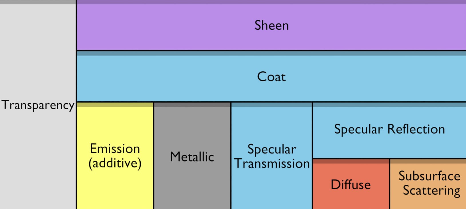
Horizontal “stacking” of components represents mixing and vertical stacking represents layering.
E.G. Diffuse and Subsurface Scattering are “horizontally stacked” meaning that you mix between them. While Specular Reflection is vertically stacked on top of Diffuse, meaning it layers on top of it.
A little bit of nuance is lost with this diagram (E.G. Emission is added to the material instead of mixed, with the exception of transparency where it’s mixed with that.)
Note: This layout is only relevant to the current state of the Principled BSDF. There are more changes coming in the future which may add more material types.
Sorry it’s not high resolution. The devtalk website automatically compresses and downscales the image. Here’s a link to a high res version of the image on Imgur: Imgur: The magic of the Internet
Note: This layout is only relevant to the current state of the Principled BSDF. There are more changes coming in the future which may add more material types, or use inputs in a different way.
I wonder if it would make sense to change the 3 subsurface radius numbers to be a subsurface color? It does seem to me that a color and a scale should be sufficient (i.e. removing subsurface strength)
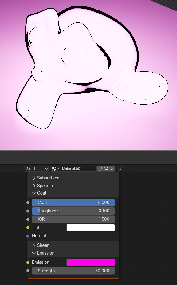
The Sheen and Coat sliders are scalers for the intensity of the Sheen and Coat layers. From now on I will only talk about the Sheen. 0 means no Sheen, 1 means apply the full sheen layer.
A value of 5 is “apply the sheen layer, multiplied by 5” . I believe this may lead to the sheen layer absorbing 5 times the amount of light it’s supposed too before reaching the layers below it. And this may result in the sheen layer adsorbing more than 100% of the light, resulting in negative values.
I’m just speculating here based on what I know. I could be wrong and there could be some other issue at play here.
Egh… Wish they’d go straight to porting the node group input kind of functionality of geometry node modifiers to the material tab instead. The material tab, as is now, is basically unusable.
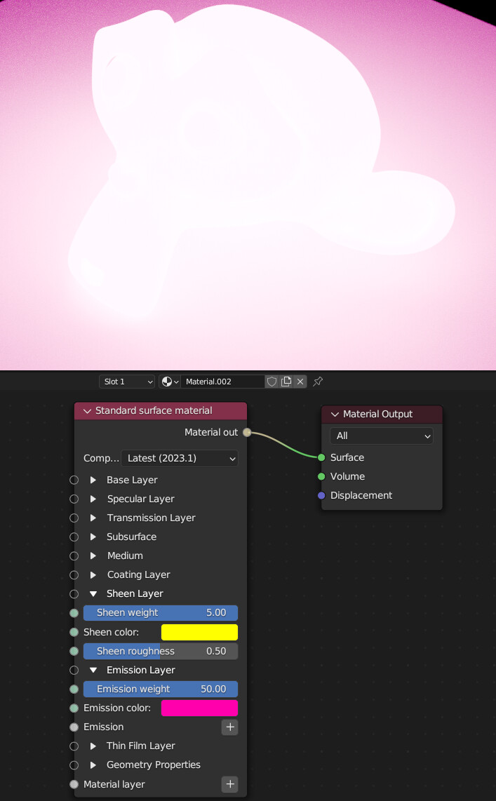
I just made a quick test in Octane for Blender (using their Standard Surface. It should use the same layering scheme as the one by Autodesk mentioned some posts above).
This is the result:
For fun I tried cranking up the Sheen on a material without emission and while it produces the velvety look, it looks like it gets clamped when > 1.0 (although you can set it to much higher numbers in the GUI).
So this seems like an unfair comparison. If Blender’s Principled clamped Sheen to 1.0 there wouldn’t be any negative numbers as well.
Setting coat or sheen to values higher than 1 is always going to give non-physically correct results, but we can clamp the sheen to avoid negative numbers.
We are following OpenPBR and this layer order is one of the differences with Standard Surface.