@Roggii and @Bobo_The_Imp , I’m just going to clarify the what’s happening with the glass.
Lights are primarily sampled in Cycles (and many other ray tracing render engines) through a process called “Next Event Estimation” (NEE). The way this works is a ray will hit a surface (E.G. The ground), and make a decision on if it should do NEE or continue with random ray tracing, and if it decides to do NEE, it then picks a light and fires a ray straight at it. If there is a object in the way that’s not transparent, that ray is considered “in shadow” for that light.
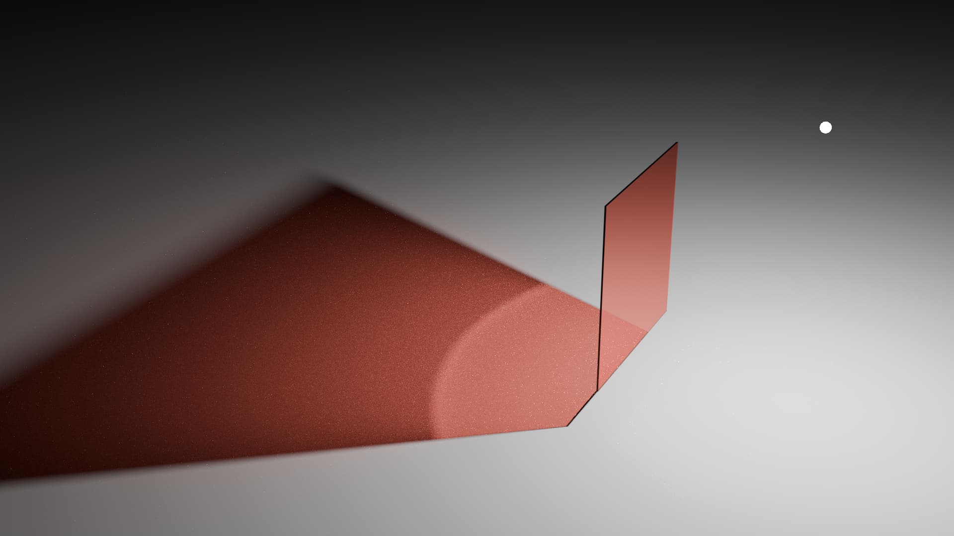
The issue with glass is that it’s not 100% transparent, so it gets classed as an obstacle and marks the ray as “in shadow” (unless you are using the architectural glass trick).
So the fix is simple right? Just don’t mark rays that hit the glass during NEE as “in shadow”? Not really.
This can be done in two main ways.
- Make it so when a NEE ray hits a piece of glass, make the glass transparent. This is basically the same as the architectural glass trick.
- Just don’t mark the ray as “in shadow” and keep the glass glass. But then you encounter an issue. The distortion caused by the glass is likely to make it so the ray misses the light. So even with this technique, things aren’t going to be improved much.
So what can be done to improve it? A few things. Of which quite a few are already in Cycles.
Make glass rough:
When a ray encounters perfectly smooth glass, the ray passes through it in accordance to Snell’s law and is likely to miss the light. But if the ray encounters a rough piece of glass, the ray can decide to trigger NEE off of that piece of glass ensuring it hits a light. This can greatly help with the transmission of light through the glass.
Sharp vs Rough Glass
Smooth Glass:
Rough Glass:
Obviously increasing the roughness of the glass isn’t great for most scenes. For example windows, which are expected to be smooth.
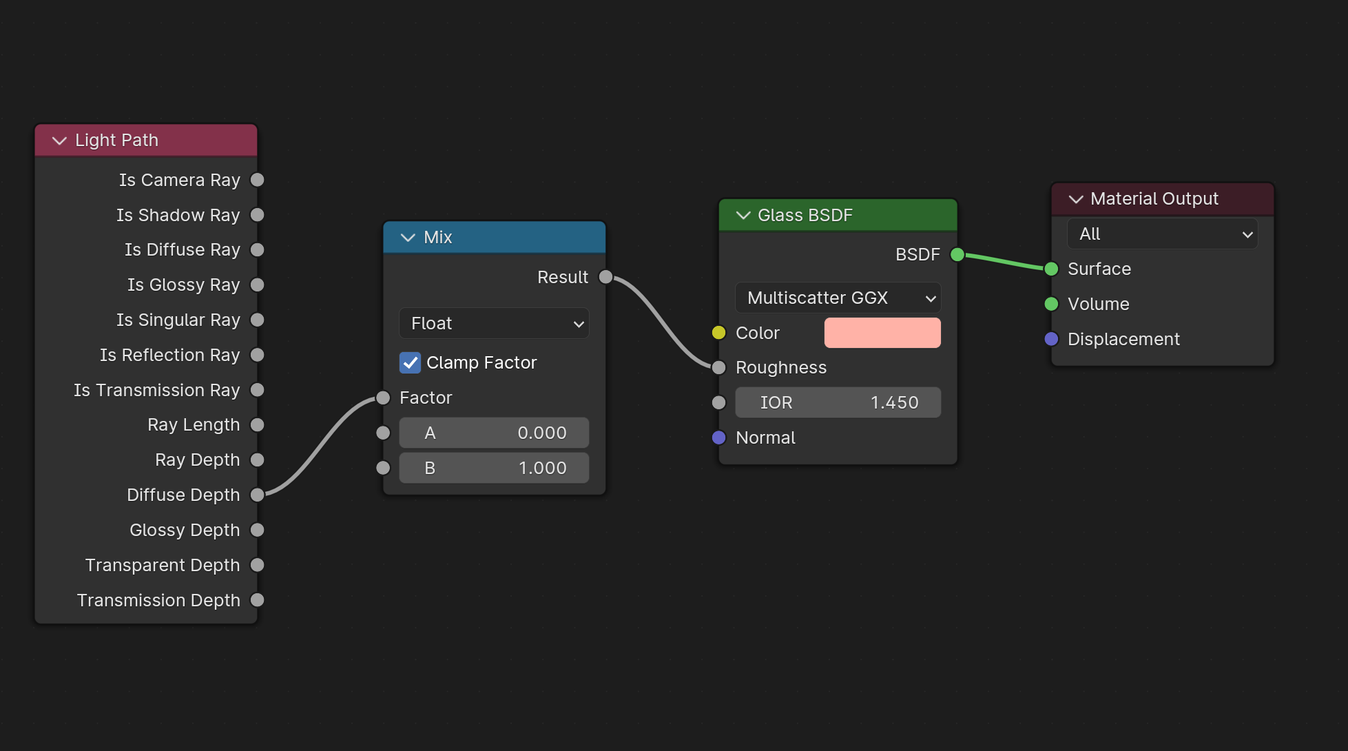
So Cycles has a feature called “Filter Glossy”. Which will increase the roughness of the glass when a ray hits it after previously hitting a diffuse surface. This allows the glass to remain smooth to the camera and certain material types, but appear rough when it’s needed the most. It works similarly (but not the same) as this setup:
This setting can be found in the Render Settings - > Light Paths -> Caustics -> Filter Glossy section.
Note: Increasing the Filter Glossy setting will decrease the accuracy of caustics through the glass. Because the caustics are being rendered as if the glass is rough.
Make it so NEE works with glass:
There is a technique to try and make NEE work with transmissive materials like glass. It’s called “Manifold Next Event Estimation”. The idea is simple. Do NEE, but take into consideration the distortion of the ray as it passes through the glass material.
Cycles has this feature. It’s known as “Shadow Caustics”.
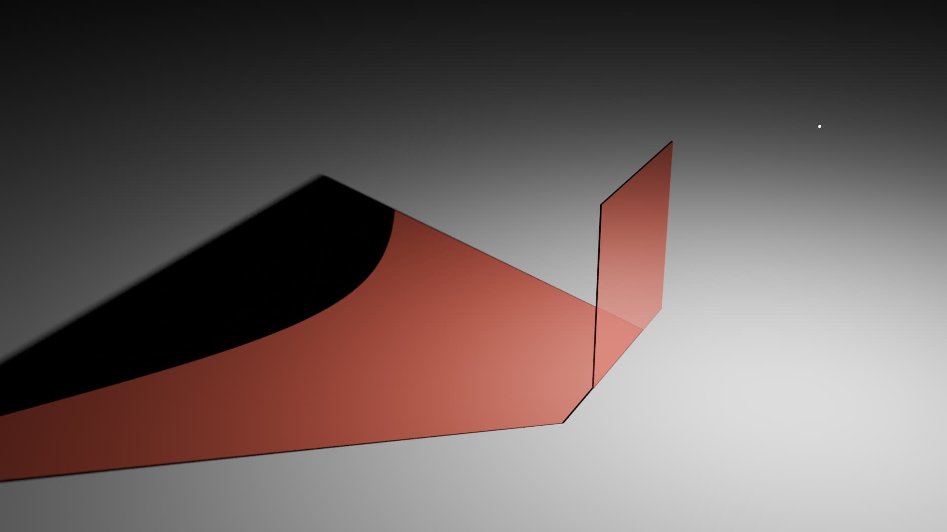
Shadow Caustics vs Normal rendering
Normal rendering:
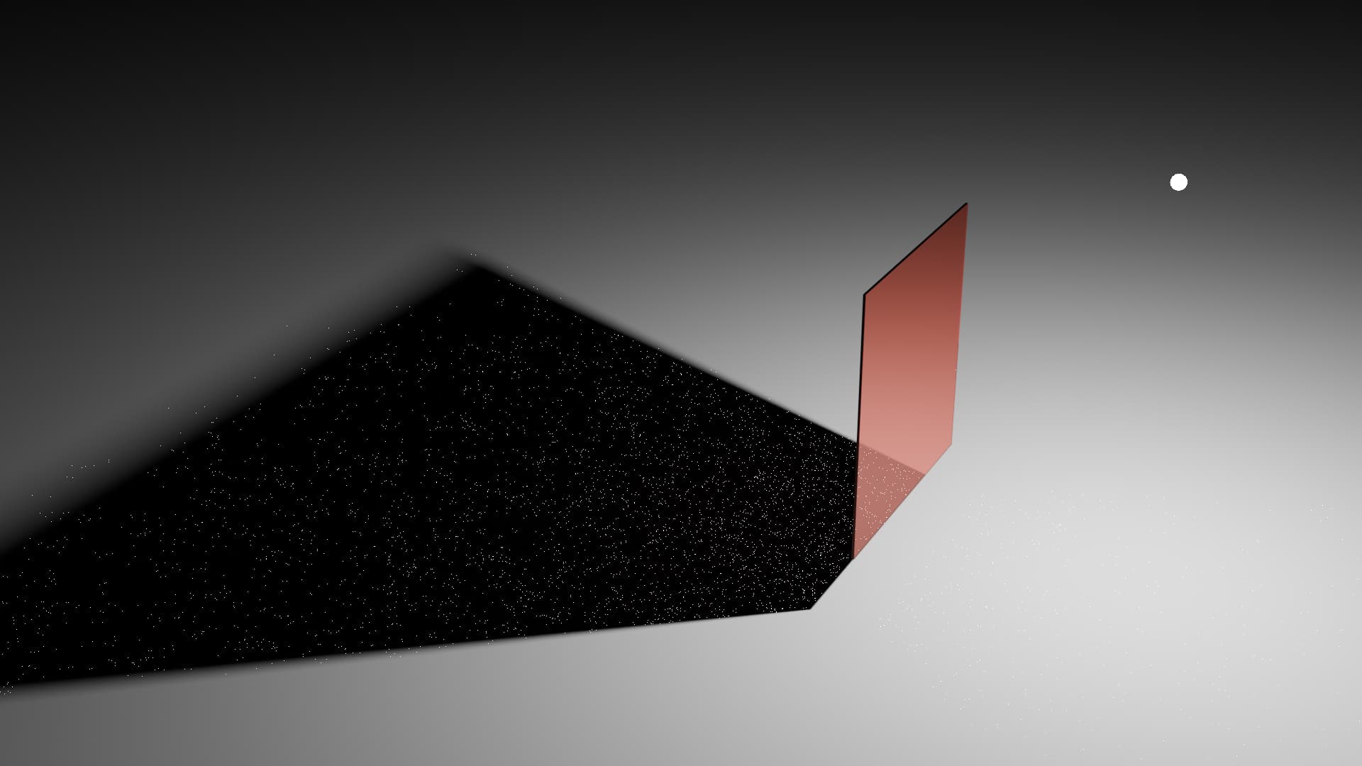
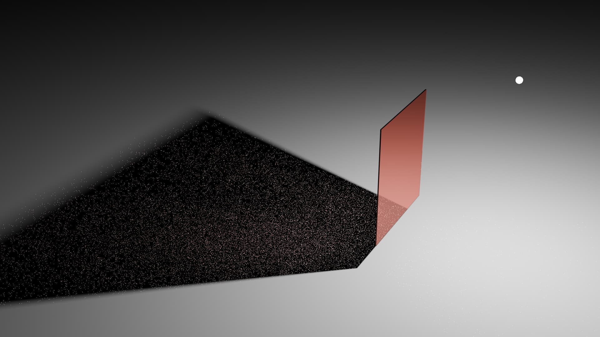
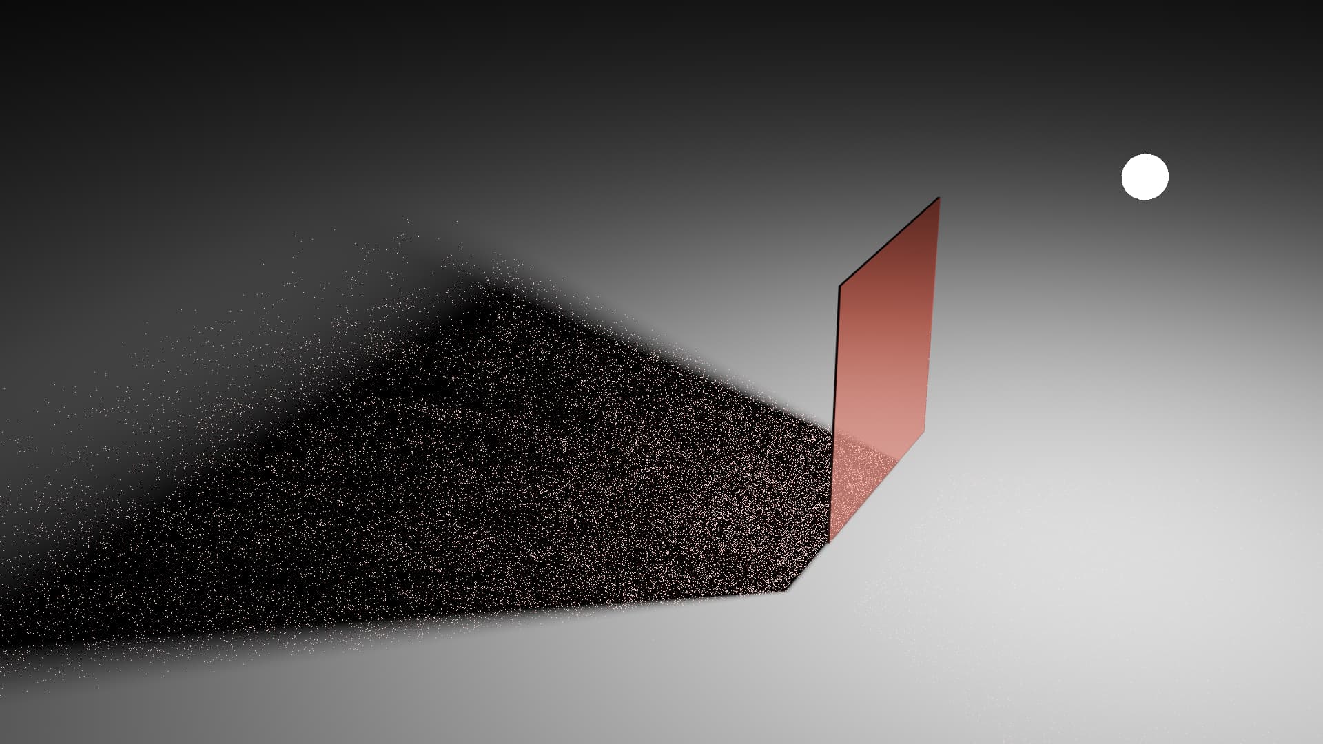
Shadow Caustics:
You will of noticed something. There’s a section of the “shadow” that is just black, when it would be expected to be red. There’s quite a few limitations with the Shadow Caustics feature, and one of them is causing that issue. I can’t remember the technical details on why this happens, but it’s a known issue and so Manifold Next Event Estimation is usually only used for specific setups (E.G. Rendering light passing through the cornea and onto the iris in an eyeball). Maybe it can be improved in the future?
Make it so the random rays are more likely to hit the light:
I mentioned earlier that when a ray hits a diffuse surface, it can decide to do NEE or continue tracing rays randomly. Well the “continue randomly” method is how a lot of the light passing through the glass is actually sampled. So what if we improve this?
There are many ways of doing it, but I’ll only mention a few.
Learn which way the light is coming from:
If the ray tracer had some way to learn which directions the light was coming from, even when bouncing off and passing through other objects, then that learned data can be used to help guide rays to focus on those important regions.
Cycles has feature for this, it’s called Path Guiding. Currently it can only be used on the CPU, but Intel is working on GPU support.
Normal vs Path Guiding
Normal Rendering:
Path Guiding:
Disclaimer: Path Guiding is not designed to solve caustics. It’s just that as a side effect of how it works, it can help with caustics solving.
Make the light easier to hit:
The main issue with randomly hitting a light through a piece of glass is that the light is so small from the perspective of the ground in the shadow of the glass, that picking random directions that actually hit the light is unlikely. So if we could make the light appear bigger to the ground, then that will increase the chance it get’s sampled. The main ways of doing this are increasing the size of the light, and moving it close to the ground object. Obviously this technique can only be applied in select situations.
Examples of the impacts of increasing light size
Small:
Medium:
Large:
And then we can combine some of these technique together.
So here’s an example showing what a small increase in light size, path guiding, and a bit of filter glossy can do.
Normal rendering vs Adjusted rendering
Original:
Slightly bigger light, path guiding, and a little bit of filter glossy:
Note: This is what changed between the original scene and the modified scene:
- Light radius was increased from 0.01m to 0.05m.
- Filter glossy was increased from 0.0 to 0.2.
- Path Guiding was enabled.
Other techniques:
There are obviously other techniques that can be applied to help out with this situation. Or modifications can be made to existing techniques to make them better.
Reverse the ray tracing direction:
The main issue we have with sampling light through a piece of glass is that it’s unlikely that a ray will hit the ground, then randomly pick a direction that actually hits the light. But what if we did it the other way? We trace rays from the light to the ground?
Well, you get a similar issue. It’s unlikely that the ray will hit the ground and pick a random direction that hits the camera.
But if you combined “light to ground” with “camera to ground” ray tracing, you can get the benefits of both approaches.
This technique is known as “bi-directional path tracing”, or a modified form of it can be used called “photon mapping”. Cycles doesn’t support these techniques. I can’t remember if there was a specific reason it isn’t supported, or if it’s just a “we haven’t gotten around to it” thing. So you’ll need to wait for a comment from a Cycles developer about that.
And just a quick recapper thing.
The glass is not broken. It does allow light through it. It’s just that depending on the scene setup and render settings, it can be hard for Cycles to sample light through the glass.
If your only desire was to sample the light more often, without using any tricks, then Path Guiding and bi-directional path tracing are the kinds of options you want to pick. Maybe increase the light size if you can.
But if you’re willing to loose some accuracy, you can adjust the filter glossy settings and use the architectural glass trick.