@toxicbits: Do you see the colorful glitches with POM and screen space reflections as well with the first implementation of POM (see first post in the thread)? I’m not really sure what is failing here. Maybe some resource limitation on AMD GPUs?
@fr002: Nice showcase video. Regarding performance: The only major issue I have seen is with very high resolution displacement texture maps that are displayed at a small scale (large step in texture space from one screen pixel to the next). This is related to the LOD/Mipmap selection issue mentioned above. The first implementation (first post in the thread) of POM (image texture only) had a special fix for this issue (manual LOD selection by the POM code). Without this fix, the same image texture performance issues could be observed. Unfortunately, adding this fix to the new implementation is difficult as there can be an arbitrary number of image textures in the displacement node tree (each with their own tree to calculate the UV inputs).
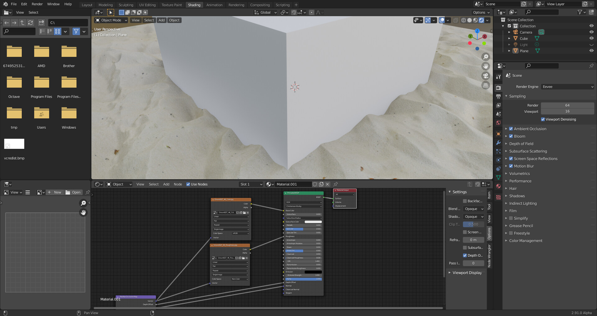
After looking at your procedural materials: I think the problem is that “Noise Texture Node” with high “Detail” parameter or “Voronoi Texture Node” are already quite expensive on their own. With the current POM implementation you approximately multiply the computation time by a factor (samples_count + 12). Here “samples_count” is the parameter given on the user interface and “12” consists of 8 fixed binary search refinement steps and 4 evaluations for the normal approximation.
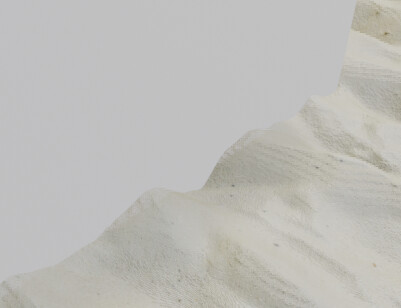
PDO intersection itself should be the same, except perhaps for some 2x2 pixel blockiness originating from texture LOD/mipmap selection when using linear texture interpolation.
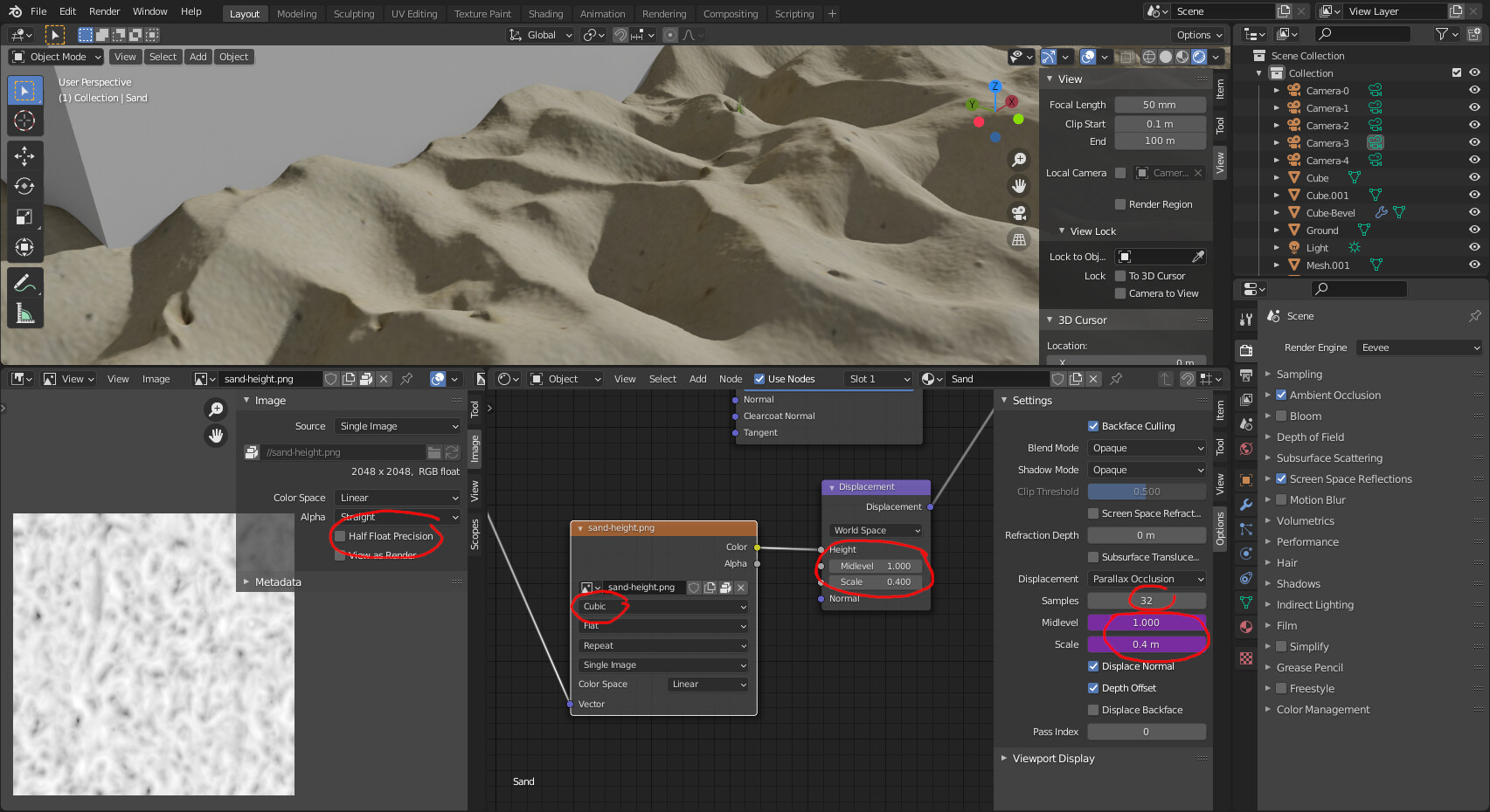
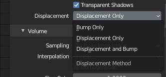
Regarding render quality with image textures, make sure you have the following settings:
“Half float precision” should be disabled on the image texture, if it uses high quality 16-bit data. The setting can be access/changed per texture in the “Image Editor”. The first image texture based POM implementation (with a new node) exposed this setting directly on the POM node. With the displacement based POM implementation you have to change it yourself for high quality results. Enabling “Half float precision” might improve performance, but can degrade the visual result (especially normals).
Use “Cubic” interpolation on the image texture nodes used in the displacement node tree. This avoids quality issues (2x2 blockiness) from LOD/mipmap selection problems and produces higher quality normals. But it is generally slower than linear and can also produce more aliasing artifacts.
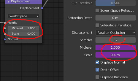
Make sure you have correct settings for Midlevel/Scale in the POM settings. With wrong settings you either waste samples (range is set to large) or clip the displacement at the top/bottom.
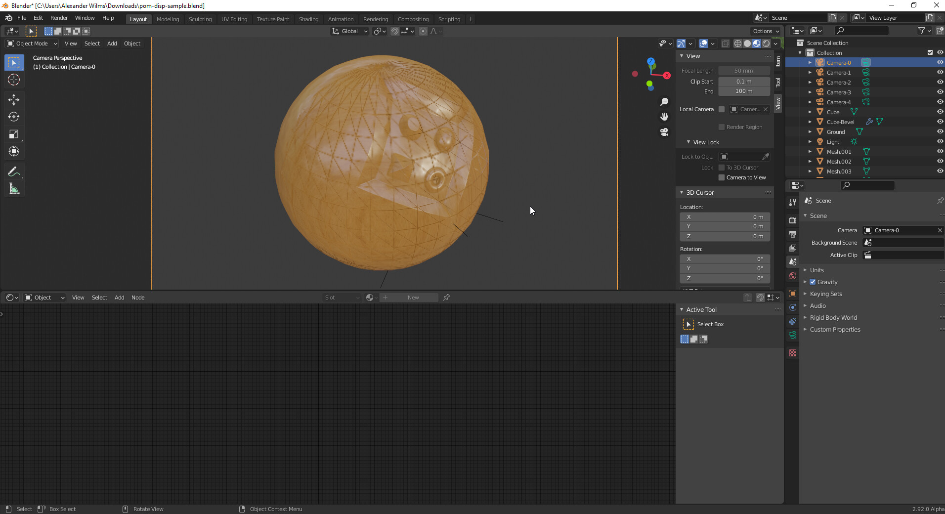
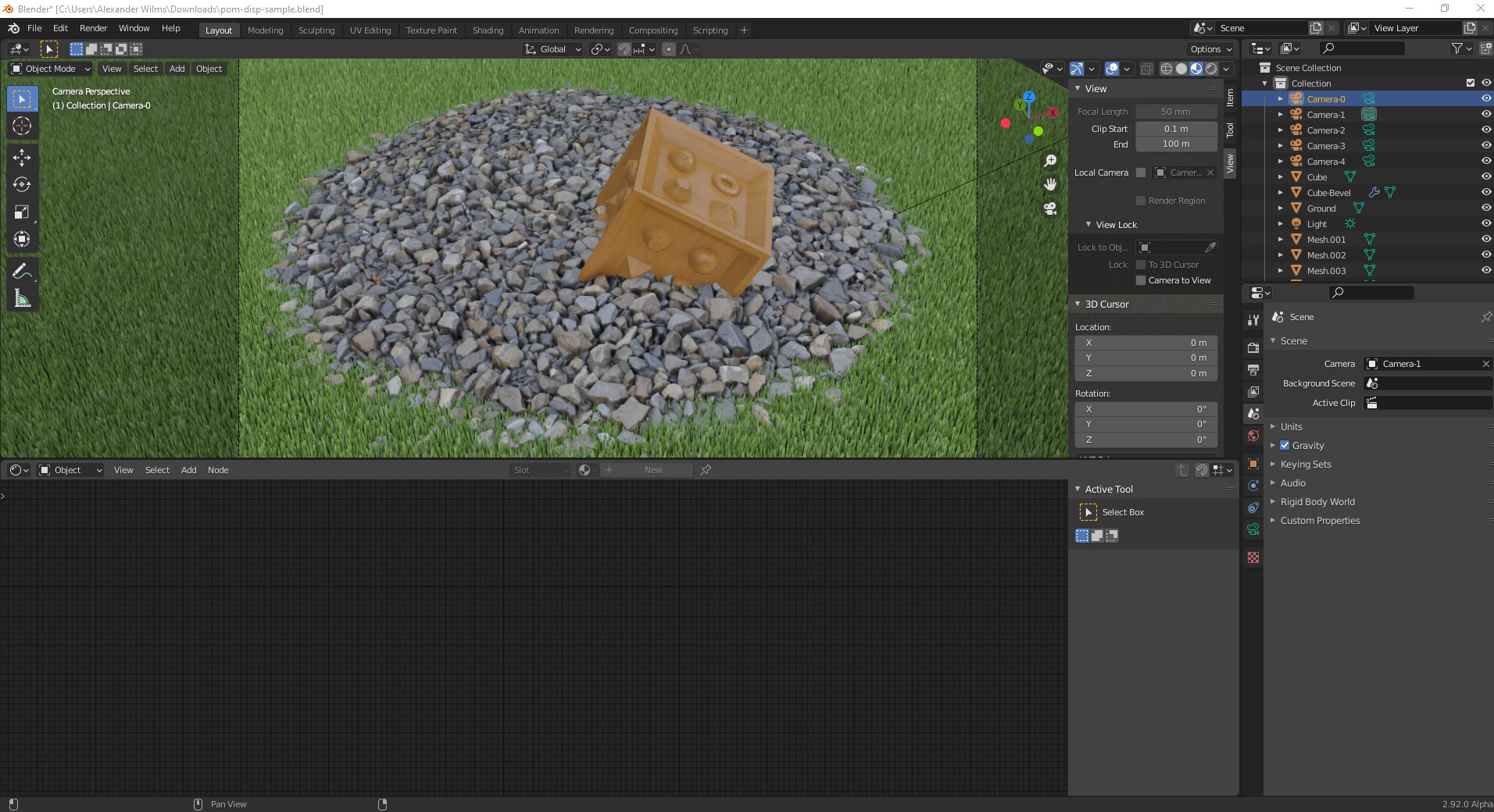
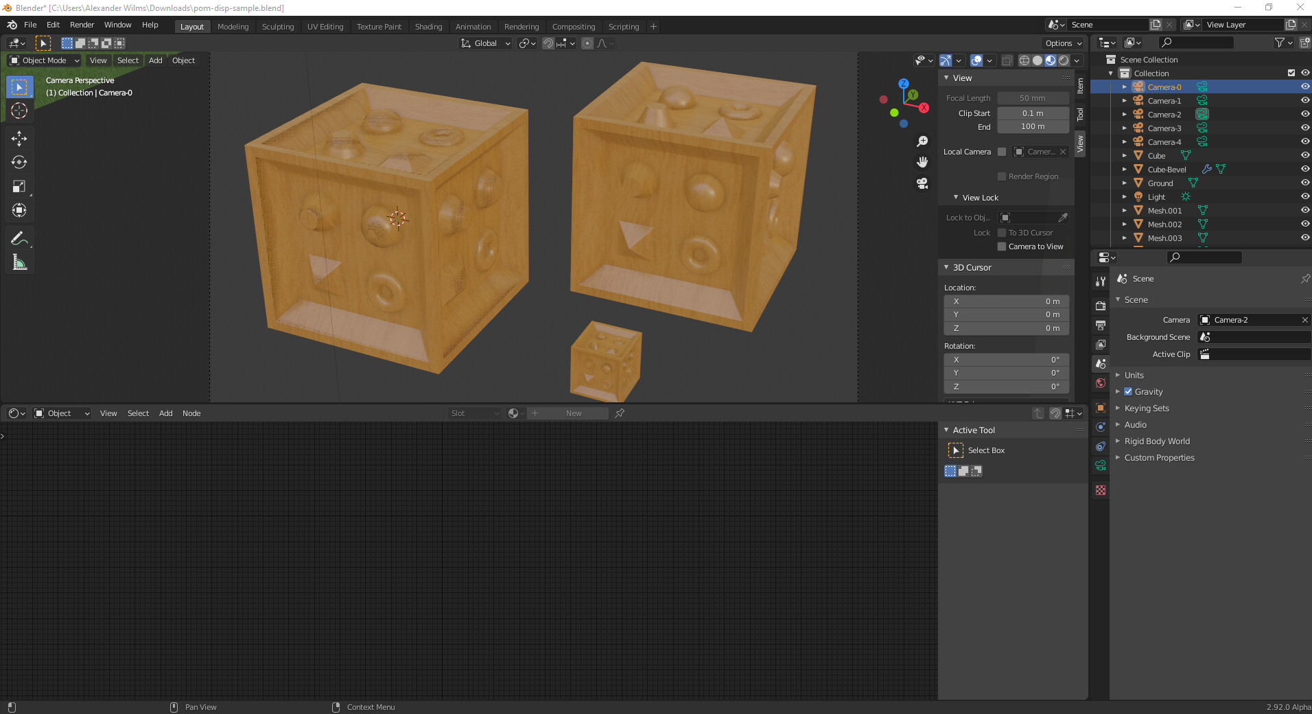
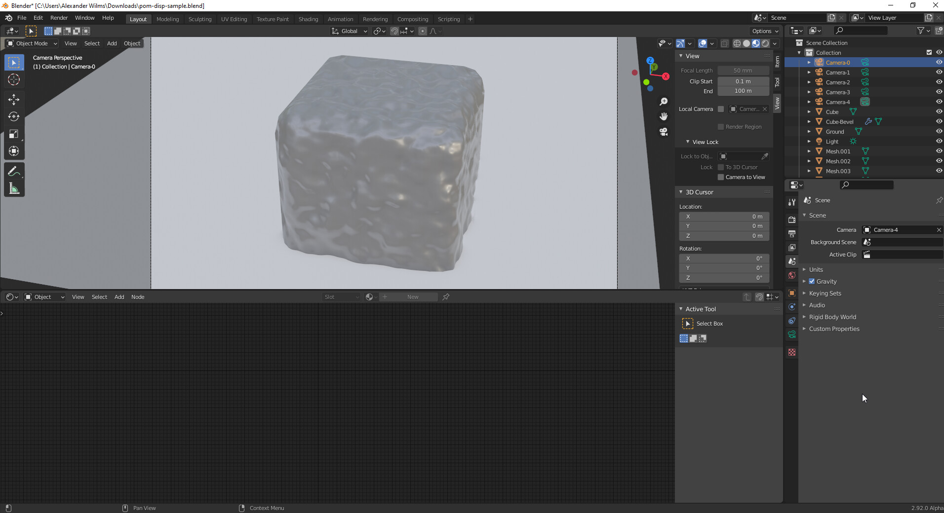
@toxicbits: Can you render the 5 camera views in the pom-disp-sample.blend file linked here https://developer.blender.org/D9792 without changing the settings in the file? It might help to better understand the issue.
I have taken a look at your video once more, and I think I can see the problem you referred to regarding the PDO intersection. There is also a strange layering artifact in your images/video. The visible layers/contour lines most likely correspond to the linear ray search steps of the POM algorithm. But I have no idea why they are visible on your system with the material being half transparent in between (at least it looks like this).
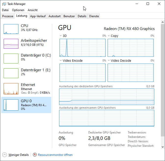
Is there anything listed in the “System Console” window of Blender (enable with: Window -> Toggle System Console)?
@mmoeller The PDO intersection looks fine if I change the interpolation method. The contour lines disappear as well. Only linear interpolation causes this problem.
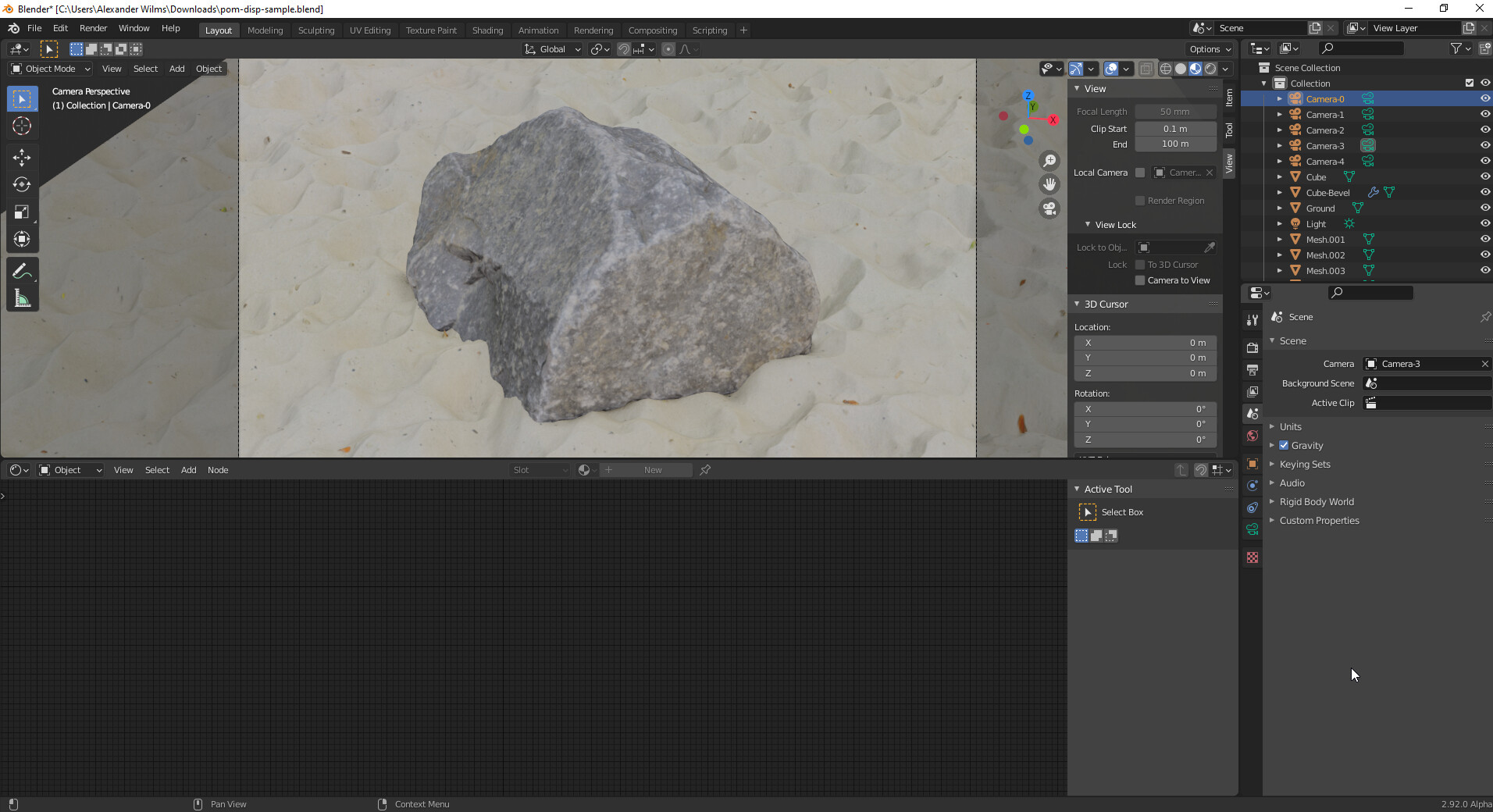
@toxicbits: Does Camera-3 not show the color splash artifacts when rendered (F12) or in rendered view? The sample file has screen space reflection enabled and seems otherwise very similar to your sample that caused problems. Have you create your sample file (that caused issues) from scratch from an empty file? Starting from a file from the previous experimental build (with the new POM and Depth Offset nodes) might cause problems.
I can see if I can generally disable LOD/mipmaps on texture fetchs when inside the POM iteration. Cubic interpolation does this already (for other reasons), but it is also more expensive overall. For some situations linear texture interpolation might be enough (if the LOD/mipmap level selection does not cause problems).
Generally a more intelligent custom LOD/mipmap selection strategy like in the original POM node based implementation would be better. But since this is quite complicated, just forcing LOD/mipmap level 0 on all texture images might be a good first step to remove the artifacts. The performance issue with high resolution displacement texture maps will still remain.
I can’t get the colorful glitches to appear in your sample file. I tried moving the view around, using linear interpolation of the height map and en- and disabling screen space reflections.
When I switch to camera 3 and try to render or use rendered view, Blender becomes unresponsive.
I created a new file from scatch and the issue still occurs. But I noticed in my sample file, the colorful glitches disappear when not using linear interpolation.
I have updated the code https://developer.blender.org/D9792 and uploaded an experimental build to https://blender.community/c/graphicall/frbbbc/ to always use the highest resolution LOD 0 for image textures with linear interpolation setting (in the displacement node tree). Image textures used in the shading part of the node tree are not affected. This should avoid some of the artifacts visible when using linear interpolation settings for displacement maps. This change might reduce performance, but the result should generally be more correct. And using the linear interpolation setting for image textures is still faster then the cubic/smart interpolation setting (which already uses LOD 0).
@toxicbits It would be great if you could test once more with this new version on your system.
Thanks. I can test it on Monday. Maybe someone else reading this has an RX 480 and can check if the older build exhibits the same issues on their system and if the new build fixes it.
This feature looks extremely cool, thanks a lot for the work! I’d like to compile it for macOS. Is there a branch I can clone or do I have to use the diff?
There isn’t a branch in the official repository. You should switch/checkout to Blender master commit c850ce93a4ebf110a41c5cce0a2bd3258182230b (20/11/2020 17:13:05) and apply the diff https://developer.blender.org/D9792
Have you got a strategy to affect the effect intensity based on the distance? Pixels that are far away from camera would have not to be displaced at all (with a distance check you discard the displacement calculation), it could be a chance somewhat to improve speed.
However these have to be tested as well if is something to be concluded. However I see lots of potential for extra control and improvements with this. Great job.
I really don’t see a reason to limit POM by distance. Unlike tessellation there is no cost associated with unnecessary subpixel detail as it’s pretty much a 1-1 relationship. Plus there is an additional cost in doing this and branching in the shader.
I’m not really sure how an automatic, efficient and correct fading/discarding of the displacement for distant geometry could be realized. The calculation cost is already greatly reduced for distant geometry, because it is a per pixel effect and distant geometry occupies less pixels.
Depending on scene setup, a lot of time is spent rendering the shadow maps. The geometry with POM, depth offset and shadow casting active has to be rendered with the POM displacement iteration shader. This is a lot more expensive than a simple depth pass (without fragment shader) for simple opaque geometry. You can easily see the difference in performance if you disable shadow casting (and/or depth offset) on the POM material.
I might look into optimizing this. It could be useful to have a separate parameter for the number of POM search steps when rendering shadow maps. The shadow part seems to tolerate (visually) missed geometry features a bit better than the fragment shading itself.
I see that there is single samples number,
maybe You should have min/max samples and lerp them based on face view angle?
Why do i have to substract midlevel ‘manualy’ from height map in nodes? I do something wrong? (same height and referenceplane 0.5 works in Machin3 nodes and UE as expected)
UI Wise:
Why this is single “Displacement” output and not separate ones?
When we will have WPO it will be same output as it is in Cycles super weird solution?
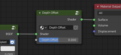
Also why is Depth offset bounded to POM? DepthOffset is awesome feature on its own and could be separate feature eg. for material blending and other stuff.
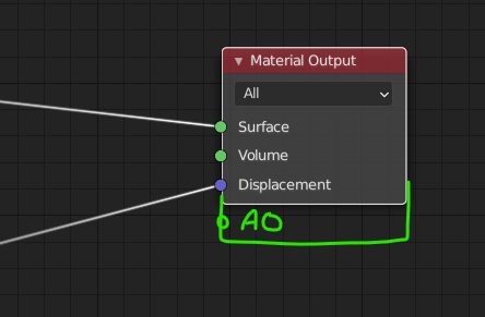
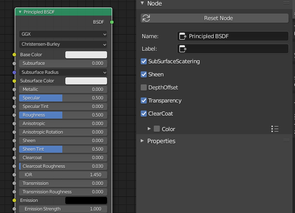
Anyway, i know its totaly unrelated, but hence You are working on this area, would you mind exposing Ambient Occlusion texture output to Material Outputs?
Currently its hardcoded to 1.0 in BSDFs (except Specular shader).
View dependent sample numbers can produce annoying artifacts for animated scenes. With the current implementation, the height of the POM “layers” created by the search samples are fixed (at least for flat base geometry). If you lerp by view angle, the layers constantly move in animated scenes. It’s possible that the randomization I have added to the search can hide this issue. I would have to retest. But generally making errors view dependent can have major drawbacks when the view is not fixed.
Maybe the intended use is not clear enough: The material “Displacement” output is a vector output. The Bump and POM implementation in Eevee just use the part of the vector in the direction of the local normal vector. The intended use is as shown here using the “Displacement” node: https://docs.blender.org/manual/en/latest/render/materials/components/displacement.html
Of course you can also do your own calculation with entirely different nodes, but this is the recommended way.
Also note the difference between the Midlevel/Scale setting on a “Displacement” node and the the Midlevel/Scale settings on the POM settings panel. The parameter on the “Displacement” node define what you get as actual displacement (in object or world space scale). The parameter on the POM settings define a space interval (always in world scale atm, maybe I should add an option for object scale as well) in which displacements can be correctly resolved/rendered using POM. Ideally the POM settings should be chosen such that you exactly cover the same space that you use with your material. If the space in the POM settings is too large, you waste POM samples. If the space is too small, the resulting displacement will be clipped (at the top or bottom). If you use the “Displacement” node with world space option (and the input is clamped to 0…1) in your displacement tree then you can just copy the parameter to the POM settings using drivers (see the POM sample file for examples).
I do not know the detailed reasoning for the current UI, I have just tried to integrate POM with the current system. Of course it could make sense to have two different outputs, one for single normal direction displacement and one for vector displacement. With multiple outputs you also raise the question what should happen if both outputs are connected (only one gets applied, a combination of both, …). Related to this is the question, whether it is really a good idea to have the shading node tree and the displacement node tree combined into one. In my opinion things would be clearer if the two are separated. But I think anything not strictly required for POM should be kept in a separate proposal.
I have removed the Depth Offset as user exposed feature to make this proposed change simpler (especially in terms of new user exposed features that would have to be supported long term). If there is a concept for exposing Depth Offset to the user (for example with a node and additional inputs as in the first implementation) that the Blender team is willing to accept, I would be ready to write the needed code (in a separate proposal). But I also understand that directly exposing very low level things like dFdx/dFdy or Depth Offset do not fit very well into a more abstracted PBR concept.
As you said, AO is unrelated, and should be looked at in a separate proposal. Also I think AO as parameter should be placed on the Shader node and not on the material output.
Oh, damn i was confused by duplicated referenceplane and scale parameters and thought that it requires scalar valuse and not vector.
Why it requires “Displacement node” and have same settings inside material?
Okay fair enough. I hop thet design of Dsiplacement inpuit will be redesigned soon.
Ok. Hmm, What if there was “Depth Offset” node with shader and offset inputs?
Would it be possible to implement like that? (And 5. AO also? I’ve asked Campbell why AO is not exposed in Principled and goal was to have separate output or something like that)
Or have enable/disable shader features for more advanced users:
The problem is, the displacement node is not required, you can create other valid displacement outputs without using it. And the displacement node is not clamped at the input. If you feed values outside the 0…1 range to the Height input, you will get displacements larger than the range given by Midlevel/Scale. For the POM code it is very difficult to reliably (by static analysis) predict the range (in world space units) that an arbitrary valid displacement node tree could output. That’s why originally I intended to add a “max displacement” and a “min displacment” parameter to the material POM settings. In practical use I realized that always converting the Midlevel/Scale parameters (which is the still the typical setup) to Min/Max parameters manually is not very convenient. For world space units the conversion is quite simple:
Min = -Midlevel * Scale
Max = Scale - Midlevel * Scale
Midlevel = -Min / (Max - Min)
Scale = Max - Min
The global Min/Max displacement (or alternatively Midlevel/Scale) information is required for the POM ray search, to know which space has to be covered. The Min/Max parameters act as a bounding “box” for the displaced geometry.
Technically this is no problem at all. In the first version I have implemented it this way, see the first post in this thread. It could be added back (should be easy) if this is something that the Blender team wants.