thank you for doing this, especially for a description of the commands
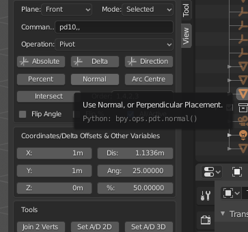
(maybe you could create tooltips for these directly in the addon gui)
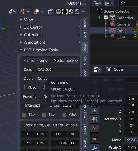
There are some there already for each button/input, but if these are not descriptive enough, please let me know and I will work on them, example below:
Cheers, Clock.
I was referring to the list of commands to insert … that is difficult to remember, for example CA0,0,0 etc …
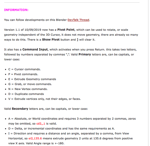
OK, sorry, I misunderstood, on my Webpage for PDT, I have this:
Which lists all the valid commands, I will of, course expand this on the help page for this part of the Add-on. Some examples:
ca1,,4 means Cursor Absolute (Global) X=1,Y=0, Z=4, if a number is omitted 0 is inserted automatically.
ed2,0.4,0.7 means Extrude Geometry Delta X=2, Delta Y=0.4, Delta Z=0.7 from the current position of each selected vertex. You can use c or C - e or E etc.
I will get on with the help as quickly as possible.
Cheers, Clock.
I’ll do that tomorrow!
another suggestion if I can, could you make the command bar more visibly separate? from the command buttons …
it took me a while to understand that they are separate things …
because I put the commands, and then I clicked on absolute or delta or other … thinking that once I entered the parameters, it took the measurements from it … 
I can put it in a separate box away from the rest, only thing is it uses the View and Mode Choices. I will think about the best place for it.
PS. You can make as many suggestions as you like, I am grateful for the feedback! ![]()
what I didn’t understand, what is the purpose of clicking on Absolute, delta, etc …?
initially I had thought, that I inserted the coordinates of the vector, and then clicking on one of these buttons, I was doing the operation based on them …
can you make a small use step to understand the mechanism?
the command bar more or less I understood how it works.
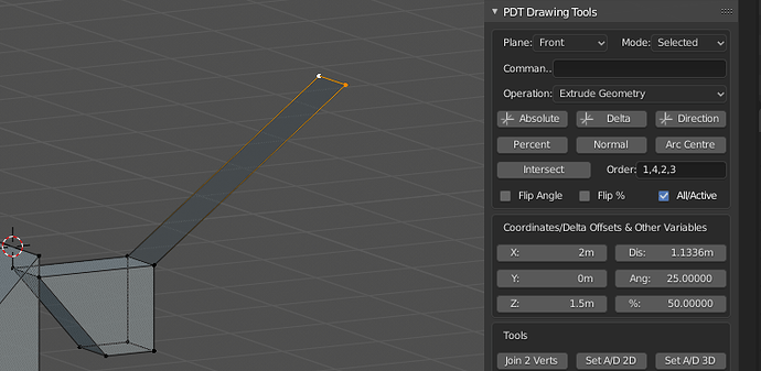
So, if you want to Extrude Geometry a Delta distance of 2,0,1.5 in Front View.
- Set Plane to Front (X is horizontal Axis, Y is depth, Z in vertical axis in this view)
- Set Operation to Extrude Geometry
- Set X to 2, Y to 0 and Z to 1.5. (Under Coordinates/Delta & Other Variables)
- Select some vertices.
- Click Delta
This is the equivalent of typing ed2,,1.5 into the command line…
Then this happens, I selected the top right two vertices of this sloped shape first:
Note! There is nothing in the Command line, but it doesn’t matter because it is ignored anyway if you click one of the buttons, like Absolute, Delta, Direction, Percent, Normal, Arc Centre, Intersect. Also note that my view is rotated, this doesn’t matter unless you are in View Plane.
Does this help?
so if I write 2, 0, 1.5 directly without the prefixes, in the command bar, I then have to click on a button to execute the operation …
No, the command must have the prefixes, set the values in these boxes:
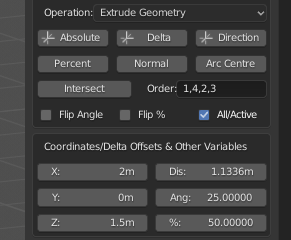
Where it says Coordinates/Delta offset & Other Variables, the buttons do not use anything in the command line, it is totally separate.
PS.
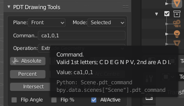
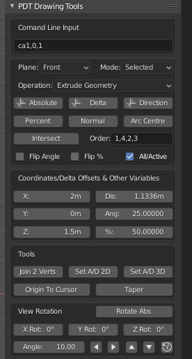
And, does this make it more obvious that the command line is totally separate from the rest:
ok, with your help and handling I’m starting to understand the real potential!
That’s good, but it is nearly 11:00 in the UK and I am tired, so I will continue with this tomorrow. ![]()
![]()
![]()
![]()
![]()
![]()
I have started on the next help page on my website… But I will now have to change this if you think the new layout is better.
EDIT:
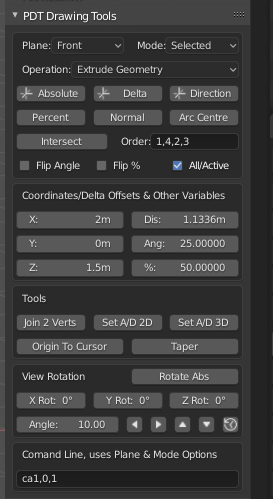
Before if fall asleep in my chair, is this a better layout for the menu:
good night!
for today may suffice, hehe
in Italy it’s now 00:20 am
edit:
I just finished my 13-hour 3D print, now I can go to sleep too 
Nice work! I have uploaded a new version with a modified menu layout and some improved Tooltips. I also have updated my help pages to reflect the new layout. Basically I have moved the Command Line away from the other functions, so as to avoid confusion between the two, It is going to take some time to complete the help pages, so please be patient!
Cheers, Clock.
Nice, much better.
Moving the commandline, I immediately realized that “variable delta offset & other coordinates” are correlated with the first box of buttons …
Maybe in this case I wouldn’t create a separator between the two areas … and maybe I would put the coordinates variables between “operation cursor” and the “commands buttons.”
I don’t know if blender allows it, but if you can put the interactive coordinates of the mouse pointer somewhere, always visible when we are in 3D view, it would be a great helper.
Currently only with the Grid we are always unaware of the measurements.
I think you should edit the first comment of this thread, and paste the description of your project here too with the link to the download page … explaining that now your project has evolved …
Currently confuses people because you started from the version with animation node addon 
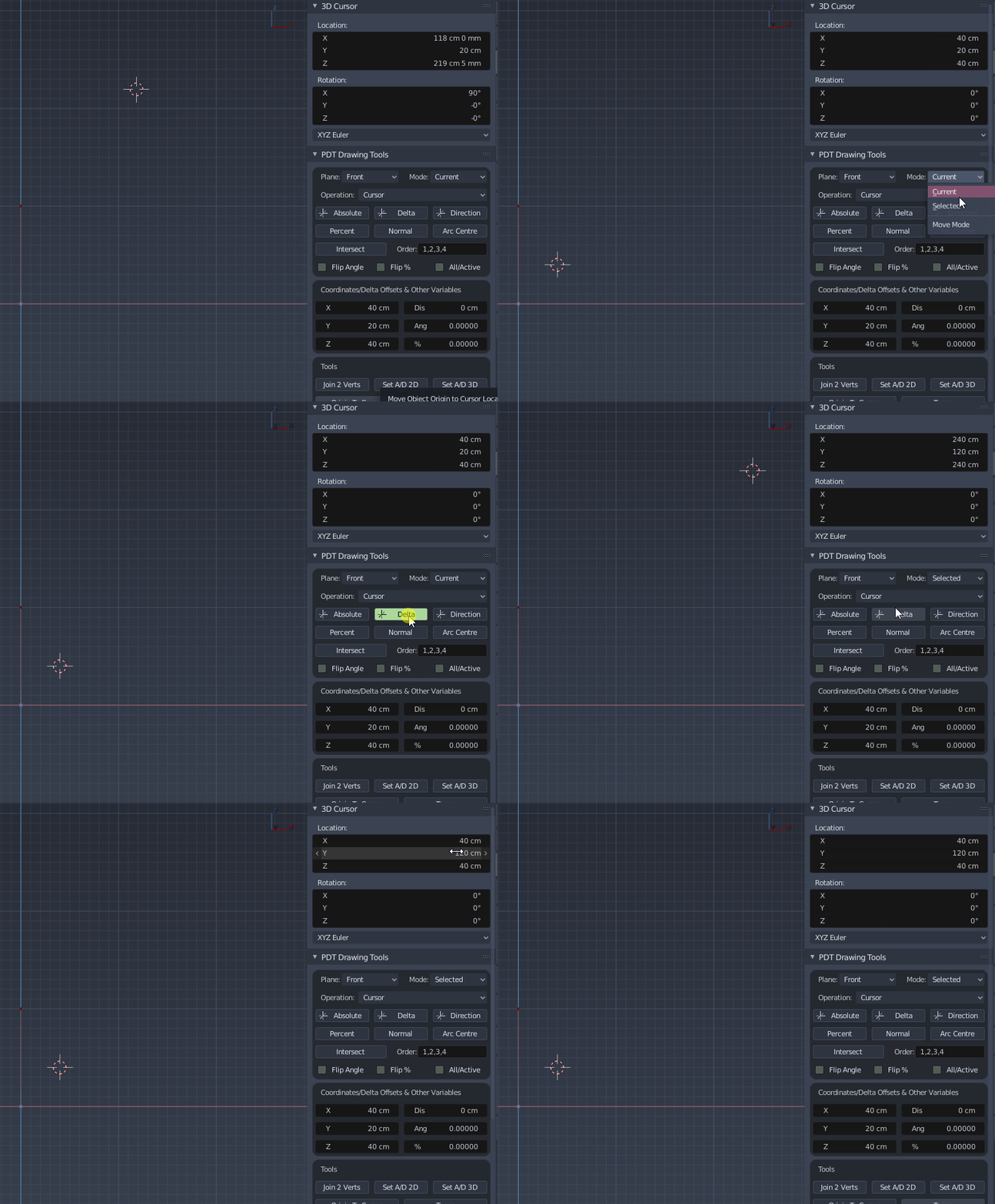
I’m understanding the difference between current and selected mode … but there’s one thing that confuses me …
selected shouldn’t be relative to the selected vertex?
if I press delta it puts me on Y 120 cm and I don’t understand where it comes from.
the selected vertex is the top one in red (the gif has killed the color)
delta is an algebra term that means “change” (don’t quote me, I’m simplifying)
you’ll see it in some derived functions written as “d” like dx/dy, and in this case it’s the rate of y (each click is adding 20y) and you can see in the screenshot that indeed, it says Y -> 20cm
if you see the gif, in “selected mode” it place the cursor at Y 120 cm and I don’t understand where that extra “100 cm” comes from …
