Hello, I have a few ideas for simulating a 2D editor in Blender. This is an example script I put together that will create a new scene called “2D” and set up an A4 sheet and an orthogonal camera to match. Also lock the 3d rotation (pan with shift+MMB). Then toggle between the 3D and the 2D scene every time it’s run… Maybe this method could be used? Just copy it to the script editor and run.
import bpy

def setup_2d_scene():
    # create 2D scene if it doesn't exist
    if bpy.data.scenes.get("2D") is None:
        bpy.data.scenes.new("2D")

    if bpy.data.cameras.get("Camera-2D") is None:
        cam = bpy.data.cameras.new("Camera-2D")
    else:
        cam = bpy.data.cameras.get("Camera-2D")

    if bpy.data.objects.get("Camera-2D") is None:
        cam_ob = bpy.data.objects.new("Camera-2D", cam)
    else:
        cam_ob = bpy.data.objects.get("Camera-2D")

    if cam_ob not in bpy.data.scenes['2D'].collection.objects.values():
        bpy.data.scenes['2D'].collection.objects.link(cam_ob)

    cam_ob.data.type = 'ORTHO'
    cam_ob.data.ortho_scale = 0.297
    cam_ob.location.xyz = (0,0,2)
    cam_ob.rotation_euler = (0,0,0)

    # A4 300dpi
    bpy.data.scenes['2D'].render.resolution_x = 3508
    bpy.data.scenes['2D'].render.resolution_y = 2480

    if bpy.data.meshes.get("Sheet") is None:
        sheet = bpy.data.meshes.new("Sheet")

        # A4 landscape size
        sX = 0.297
        sY = 0.210

        verts = [
            (-sX/2, -sY/2, 0),
            (-sX/2, sY/2, 0),
            (sX/2, sY/2, 0),
            (sX/2, -sY/2, 0)
        ]
        faces = [(0,1,2,3)]

        sheet.from_pydata(verts, [], faces)
        sheet.update(calc_edges=True)
    else:
        sheet = bpy.data.meshes.get("Sheet")

    if bpy.data.objects.get("Sheet") is None:
        sheet_ob = bpy.data.objects.new("Sheet", sheet)
    else:
        sheet_ob = bpy.data.objects['Sheet']

    if sheet_ob not in bpy.data.scenes['2D'].collection.objects.values():
        bpy.data.scenes['2D'].collection.objects.link(sheet_ob)


def toggle_2d():
    if bpy.context.window.scene.name == 'Scene':
        setup_2d_scene()

        # switch to 2D scene
        bpy.context.window.scene = bpy.data.scenes['2D']

        for area in bpy.context.screen.areas:
            if area.type == 'VIEW_3D':
                area.spaces.active.region_3d.lock_rotation = True
                area.spaces.active.region_3d.view_perspective = 'CAMERA'
    else:
        bpy.context.window.scene = bpy.data.scenes['Scene']
        for area in bpy.context.screen.areas:
            if area.type == 'VIEW_3D':
                area.spaces.active.region_3d.lock_rotation = False
                area.spaces.active.region_3d.view_perspective = 'PERSP'

toggle_2d()
Thank you - we are nearing the end of a major Refactoring exercise just now, but will look at this very shortly. We will want to add options for different drawing sizes up to A0 and Custom size. We will want to use this code, so can we have permission to build it into our next development phase please?
We are anticipating using 3D objects combined with MeasureIt-Arch routines to show dimensions and hidden lines. This work of yours will give us the basis for drawing layouts.
We have now released v1.2.0 - not much in the way of new functions, but a major internal improvement in terms of code structure. Some obscure and annoying little niggles have been ironed out and now all functions called from buttons display the equivalent Command Line entry in that section of the UI.
We have also completed a major renaming of variables to make the code easier to read, along with much more strict compliance to Pylint & Black formatters. From now on I have promised @ermo that I will check any new code for compliance, readability and structure & maintain good Docstrings…
The new version is on our GitHub, but there are still some issues getting to the Blender Servers, fingers crossed the miscreants who launched the DDoS attacks have crawled back into their filth pits.
Full Render from the Camera you setup in your script
Dead simple, but it shows how your script could be used to make a drawing, we will want to add different drawing sizes and orientations (Landscape & Portrait) - it’s a start. I have not added any hidden lines, or dimensions yet. Eventually I will use MeasureIt-Arch to produce a line drawing, but I don’t have time for that just now.
Nice, no problem using my code, I’m just happy if it can be helpful in some way. One suggestion is that you can use a material with emitter fully white (or whatever color you want) on the sheet objects, and also set the world material to black.
I am looking at adding a material in the script and adding suitably rotated lamp, for the render above, I used a Sun Strength 2 rotated 40 degrees about Y axis, gives a good uniform lighting and differentiation on the Iso view. We will work on this over the next few weeks and post results here.
My original idea was that some kind of “2d view object” could be placed in the 3d view and then the script would cut, extract edges and flatten them and then place them on the sheet. I have a script that will do the cutting and flattening parts if you are interested to see it. This means that shaded views cannot be placed ofcourse but in general mechanical drawings don’t have shaded views anyway. The advantage is that you could use emitter materials to get perfectly white/black sheets which look more professional. And also maybe in the future save the extracted lines to SVG, DXF or some other format.
Certainly would be - does this create entities that render? MeasureIt-Arch creates GL graphics and has a render option that will produce an image to composit with the background. It also lets you create dashed lines and you can set a material that renders faces white the same as the background.
In my early trials, I used a white background, so no “sheet” object as such. I am also looking at grease pencil to do drawing borders - there are lots of ideas just now that need looking at and a roadmap for progress needs to be defined.
Cheers, Clock.
EDIT:
@BrendonMurphy - are you still interested in us taking on maintenance of MeshTools? I think you mentioned this later on last year… If so, can we have a conversation on this, either here, Chat, or PM?
Yes, you’re right, there are many ways to do this… I will see when I get some time to make a runnable version of my script. But no now that you mention it, it doesn’t create renderable objects. I used it to export lines to DXF.
This is probably a daft thing to do, but I had a go at a little tutorial, there is no commentary yet, I know this would help, but any critiques, either constructive, or down right rude and abusive would be gratefully received:
The idea was to show a basic introduction and workflow, nothing too fancy as this is the first one I have actually managed to finish…
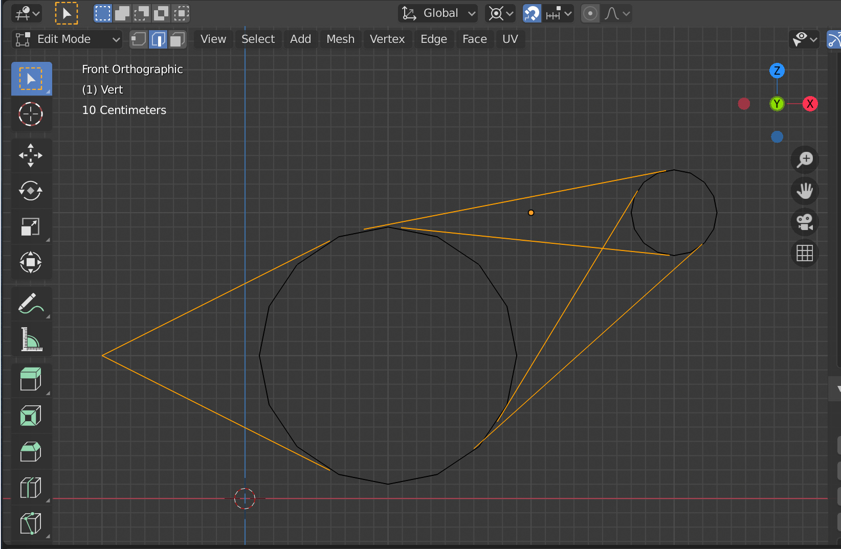
Following a feature request by email from my website, I did a little work involving some difficult sums and serious increase in brain temperature, I came up with this:
So, two circles at any location and diameter - produce all six possible tangents from a given location and the inner and outer inter-circle tangents. Looks like we can now think about writing a specification for a sub-set of tangent routines.
I should appreciate some feedback on what people might want in the way of tangent routines to incorporate into the specification.
Cheers, Clock.
EDIT:
The bonus is that I also get the intersect points for both inner and outer tangents.
Is there some easy way to get the precision value (epsilon) for single precision floats in Python, similar to sys.float_info.epsilon is for double precision? I’m currently just using the value from Wikipedia Machine epsilon (with a small safety margin).
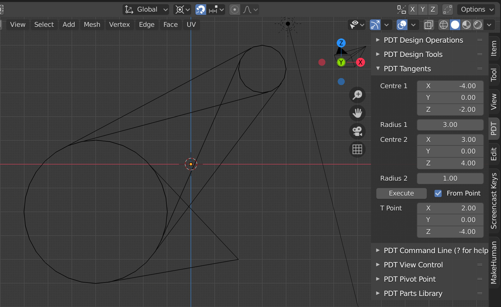
OK, some decisions need to be made, bearing in mind that Blender does not store Arcs or Circles - just chains of edges that represent these features. In order to form tangents, one needs to know the following:
Centre of Arc/Circle 1
Radius of Arc/Circle 1
Centre of Arc/Circle 2
Radius of Arc/Circle 2
Therefore I need to have these entered and stored in the UI. One option is that I have, on the UI, two Vectors and two Floats and then set the vectors by entering values, by locating the centre of an arc, or by using cursor position, the later two would be done by adding buttons to act on selections. The radii can be set by interrogating the arcs, as we already do, or by entering a figure.
Would this approach be acceptable? Would you like a different approach? Thoughts are most welcome and don’t be shy!
Cheers, Einstein.
EDIT:
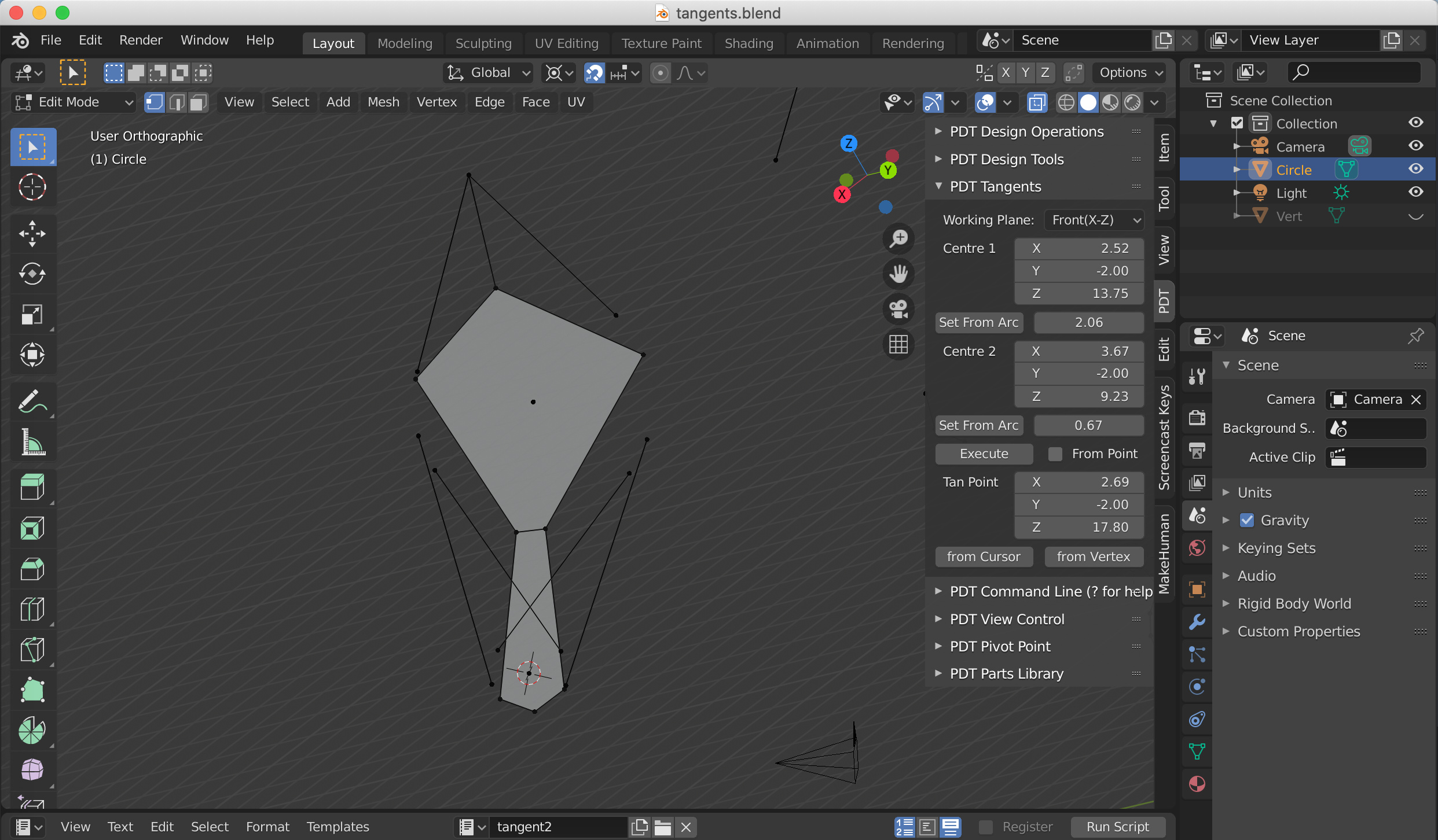
All the maths is now sorted to calculate the inner and outer tangents.
Edit again:
Here is some code to get the X locations of the first two outer tangent points:
@ermo is going to go absolutely nuts when he sees my variable names, but I will alter these before I release anything on un-suspecting users. I have to use this format of code repeatedly, with alterations, to get all 8 points for inner and outer tangents…
I don’t think there is a way to get that value from Python. The value you are using is very likely to be fine on every machine that Blender runs on, for the foreseeable future.
Now we need to think about the workflow and such matters, thoughts please?
Cheers, Clock.
PS. I need to rest for a while - grey matter is overheating. There are no DocStrings yet, or all the stuff that @ermo will insist (rightly so) that I do to the code…
PPS. At the moment it gives you Inner and Outer Tangents - all of them and you would delete the ones you don’t want, this is far easier than trying to work out which ones you do want.
One approach could be to treat every contiguous group of selected points either like a circle or an arc, and abstract from them the radius and position (and arc/circle normal?) parameters. Not sure exactly the math to use, and maybe you’ve already done it this way.
The angle between consecutive edges and their lengths could probably give the circle center. Intersecting lines perpendicular to each edge could do it too. Then the radius could be the average distance from the center to the points.
It would definitely be nice to avoid having to manually enter information about the existing circles/arcs. I think this method would make it possible.
That is going to be my next step, I already have all the code I need from the Arc Centre command in PDT Design - just need to call those routines so you can just select three vertices on any arc and it will fill in the centre and radius. After I have a rest!
Thanks for the comment, Clock.
EDIT:
On the maths front I do the Arc Centre and Radius with Numpy Arrays & Routines…