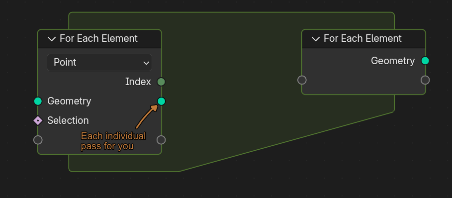
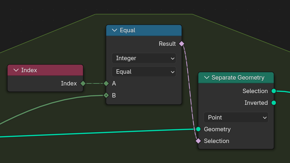
Yup that works, I just feel that separating everything by it’s index is something we will need to do virtually every time, so it would be nice if it just did it for you:
We were considering to split up the geometry into single-element pieces. Part of that was also implemented already. It’s currently not part of the patch because we’re not sure yet if we can make this possible in a way that is less detrimental for performance and/or more general.
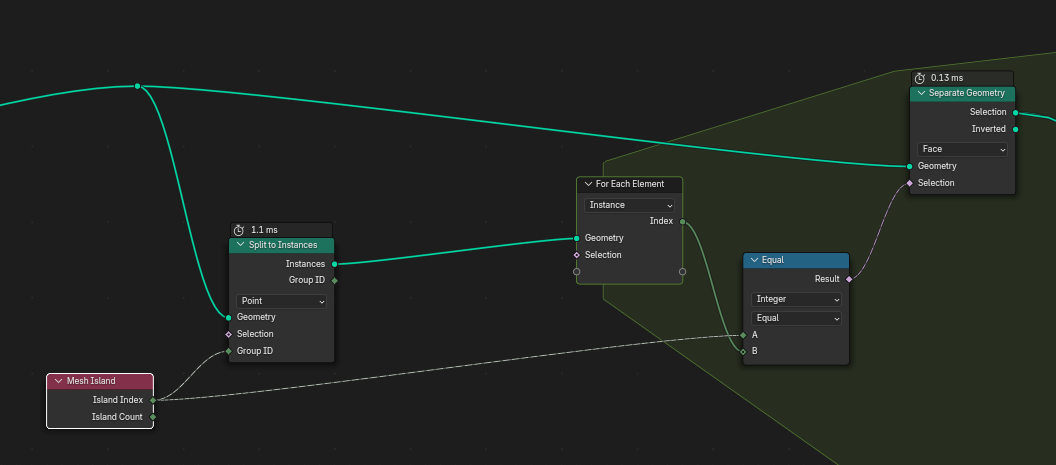
For now it may be more efficient to split each curve into its own instance first (with the Split to Instances node) and then iterate over those.
It’s only intentional in the sense that it is a known limitation of the current implementation, but not of the overall design. I’ll make that work eventually, but not sure yet in which release.
because quite frankly I feel like this will need to be done 50% of the time. Of course there are plenty of other scenarios where this is not needed, like your first example, and maybe the worry is there would be a performance hit for these other scenarios just to accommodate times where you do need to separate everything?
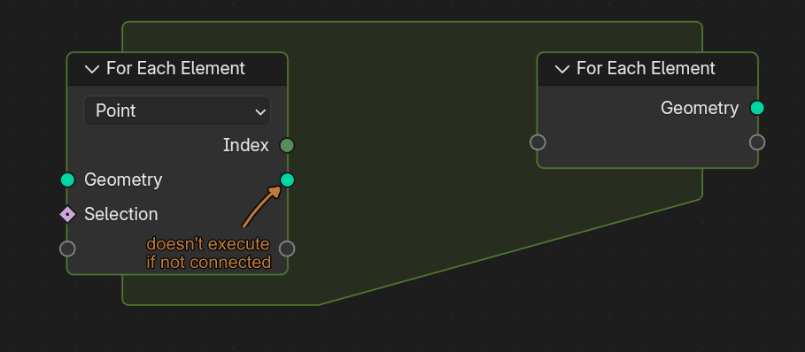
Perhaps if that geometry output doesn’t execute if it is not connected that would serve more types of scenarios? Like so:
I just strongly feel it is such a common use case of the for each loop that it feels a bit bizarre without it, it might even confuse beginners to geometry nodes.
Using Repeat Zone its possible to remesh each individual mesh island of geometry (to avoid fusion of islands if it necessary). Separate Geometry node separates one island per iteration.
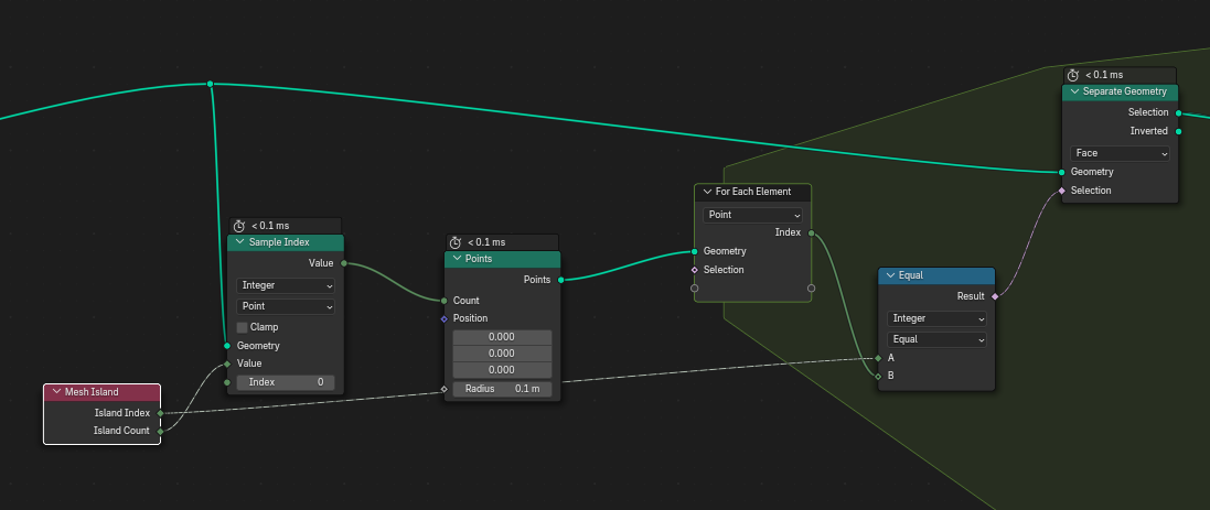
Can’t figure out how to recreate this principle with For each loop without geometry sockets
Hmm, I think we need a “for every Island” on the for each loop to do that without being very inventive. Or perhaps a group ID on the for each loop? Houdini has a separate for each loop called “for every connected primitive” that would do this.
I like the design but I do agree with @Bobo_The_Imp and @Finally_Free that a for each “group ID” (or something along those lines) element type would come in handy.
The rest of geometry nodes could also benefit from such a domain type but I also feel like it would break the design a bit since it is more of an attribute than a domain type? It would also require a new “set Group ID” node.
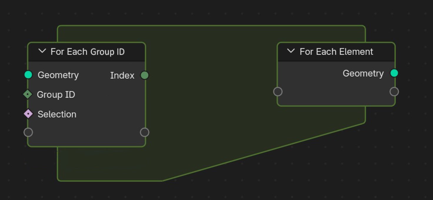
Or perhaps that should be its own seperate node? a “For Each Group ID”?
After uploading the mockup I realized that the output “index” might not really be that usefull if the first node would just output the geometry of the iteration.
I’m not sure about the usefulness of the “selection” input.
The second node would need the input socket for the output geometry?
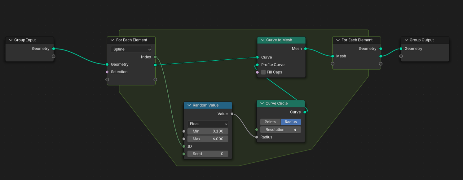
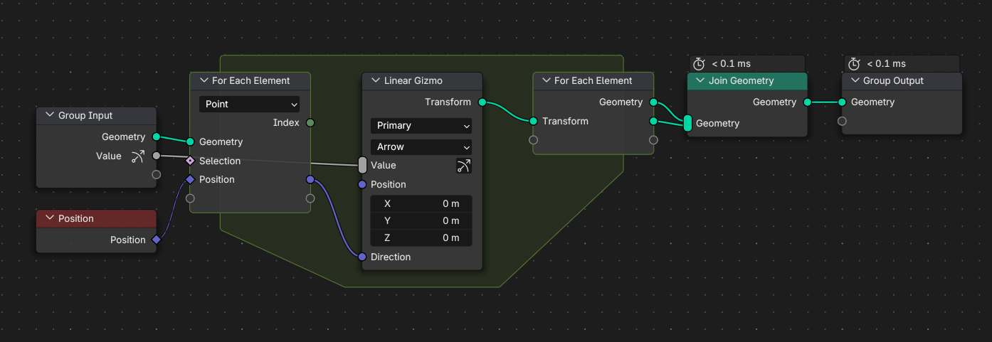
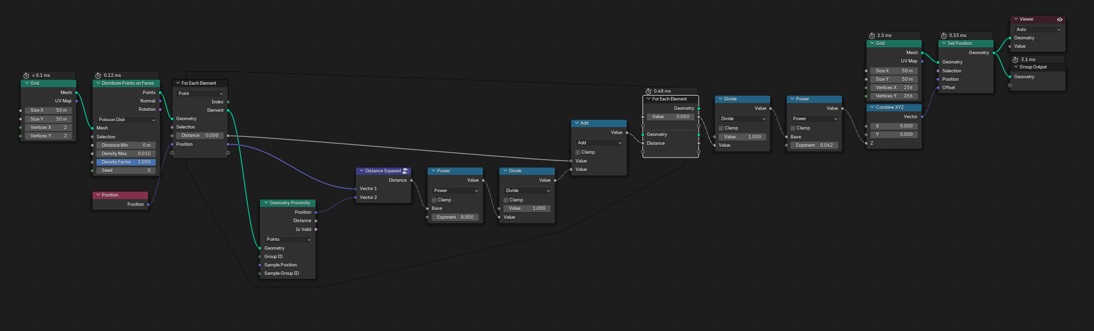
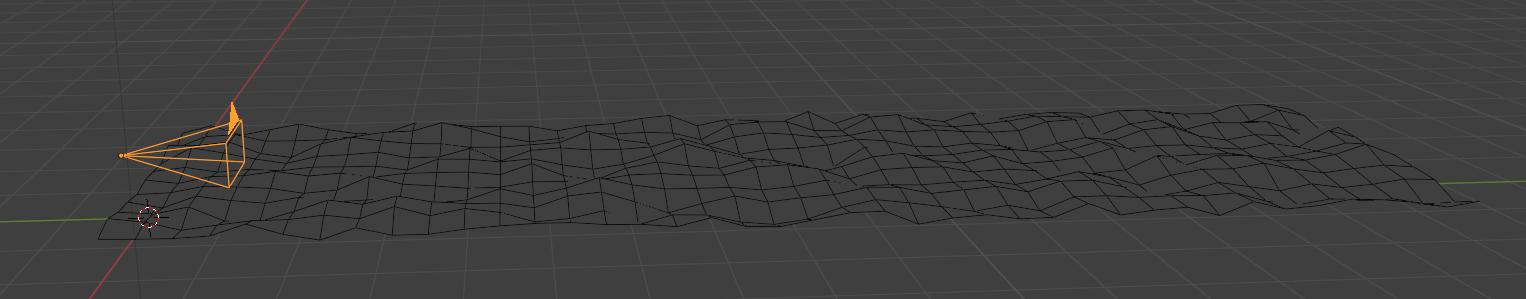
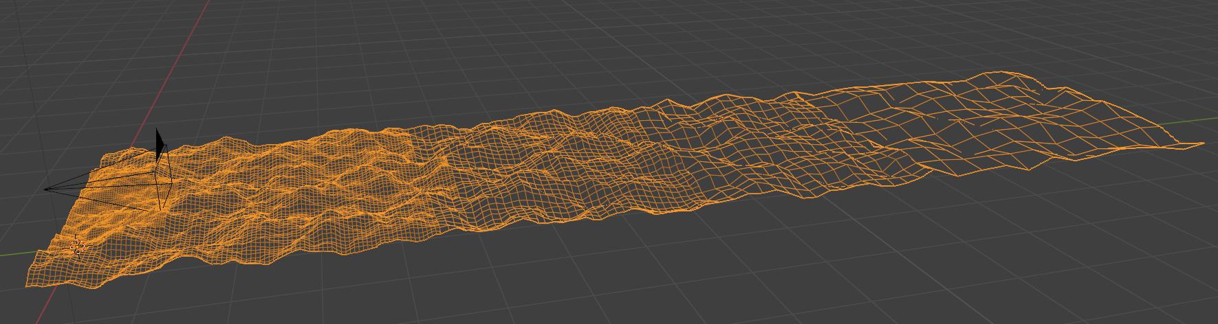
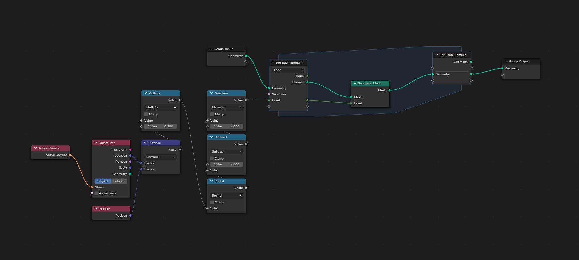
Otherwise I really like the design and here is an example of how I used it to create a “locate nth nearest point” setup.
If you look in the blog post about the design from the last workshop you’ll find that that is exactly something that is planned.
This is just the first type of for each loop, iterating over elements of the domains, there will be other types.
Great to hear that there will be more types along the line and starting with the current type makes sense since it will show what kind of other types will be needed
When developing new features sometimes it can be useful to know what users are doing, or planning to do with it to help gauge which direction to develop it or surrounding tools. So I thought I’d write up about my use case from my earlier comment
Hidden text just so the message isn't long by default.
Summary of task:
A house is planned to be constructed near a walking track and a lake, and in a area with strict visual requirements (The house should blend into the environment). One of the concern points was that people on the walking track may get sunstrike from the light of the sun reflecting off the windows of the house, ruining the “blending into the environment” aspect. I had to figure out a method to identify if this could actually happen.
Goal:
Given some geometry that represent windows, figure out if sun light could bounce off them onto a specific area.
My planned approach:
Calculate the area of the sky that the sun could be in and distrobute points across it. The points represent possible sun locations, and the more densly packed these points were, the less likely I would be to miss a edge case.
I calculated the area the sun could be in, and turn it into a mesh by modifying a addon.
Distrobute points accross the window geometry. These are points which the sun will reflect off of. The more densily packed these are, the less likely I would be to miss a edge case.
For each point on the windows, I would take all the “sun points” and compute where they would be after reflecting off the window, and highlight any that are in the area of concern.
The for each element node worked perfectly for this use case.
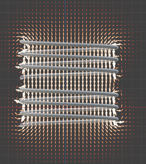
@jacqueslucke many thanks for implementing for each nodes. I have been testing it with my nodes ElectroMag Nodes for calculating and visualising magnetic fields of coils and I wanted to share my findings.
ElectroMag Nodes essentially uses Biot-Savart’s law to calculate the magnetic field of a coil. The coil geometry is a curve defined by the user, then the mangnetic field is calculated on a 2D grid that the user places anywhere. Each ‘sample’ point on the gird needs to sum the magnetic field contribution of all segments of the coil curve.
The way it is done now in Geometry Nodes is first duplicating the coil curve by the total number of grid sample points, each duplicated curve is given a ‘duplicate index ID’ to associate it with a grid sample point, and then each point on the grid uses the Accumulate Field node or the Attribute Statistic node to sum the magnetic. This approach might be considered as a “parallel loop” calculation, and certainly takes a lot of memory.
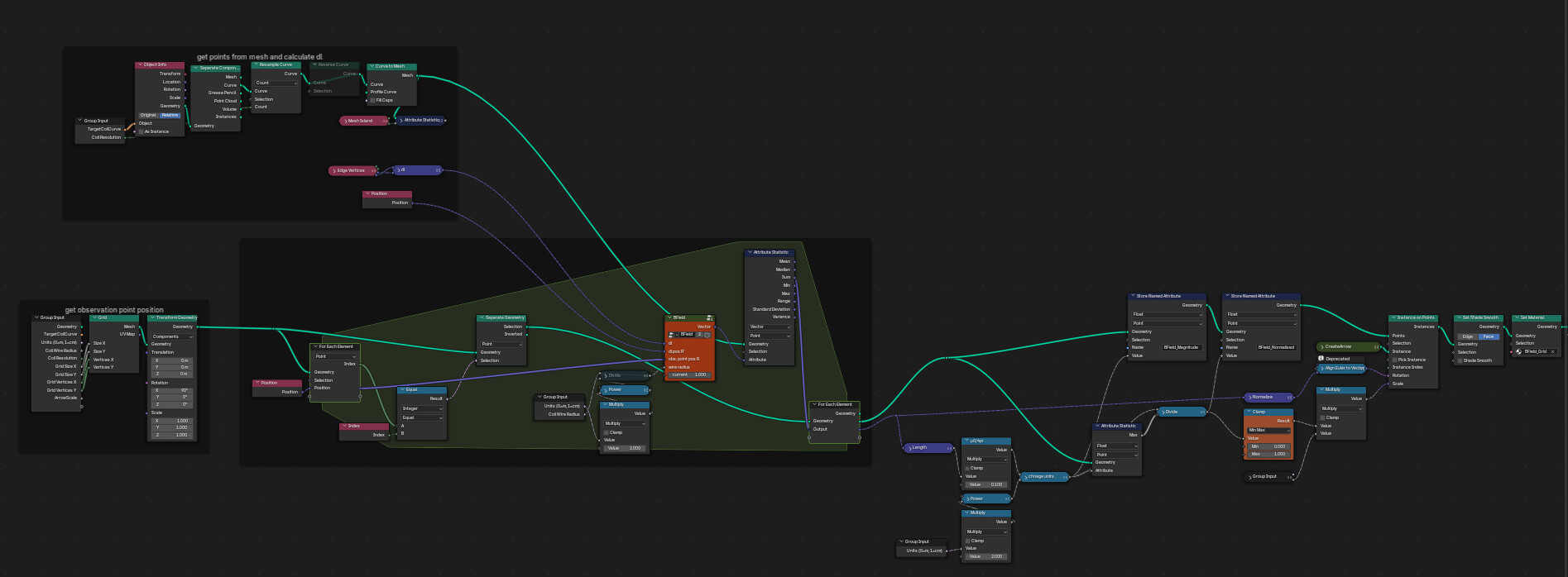
Now I was able to use the for each node successfully, and the node setup is much more simpler and easier to understand compared to what I had, however I am noticing that the peformaing and timings when using for each nodes is much slower, perhaps up to 10 times slower than my ‘parallel approach’ which is suprising to me. I wonder if there are any further optmisations that can be done?
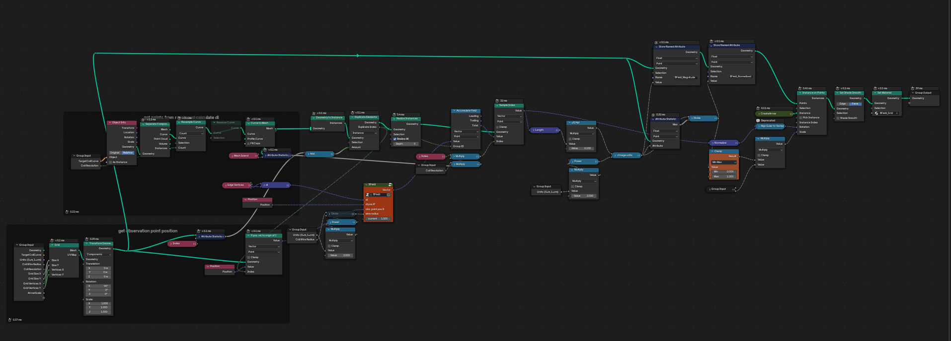
Below are screenshots shows the node setup for plotting the magnetic field of a solenoid with the ‘parallel approach’ and with the for each node setup. I have also linked the blend files.
Current implementation - parallel approach (blend file here)
In most cases right now, when you can build something without the for-each zone, that will be faster than using the new zone. The per-element overhead in the for-each zone is much larger than in existing field evaluation. This can still partially be optimized to have the same performance when only doing number crunching.
What will likely always remain a lot slower is processing many tiny geometries except of fewer big ones. If you care about performance, it will be important to process larger chunks at once to reduce the per-element overhead. This is not really something that geometry nodes can solve for you automagically.
Besides that, there are also some inefficiencies in the setup.
The Separate Geometry node currently always has to do iterate over the entire geometry at least once, so doing it for every element has O(n^2) complexity. This might be optimized at some point but it requires deeper changes to selection evaluations.
It looks like the Separate Geometry node is not even necessary in your setup. Instead of outputting a new geometry geometry with one element from each iteration, you can just write the sum as new attribute on the incoming geometry. You don’t have to add an additional geometry output.
Note that such space-fields computations like gravity / boid / magnetic / pseudo water pressure will be much faster in way of using dichotomous approximations which should be built-in as fast small and atomic building block so such use case will not be real in the long term since this takes n^x compixity.
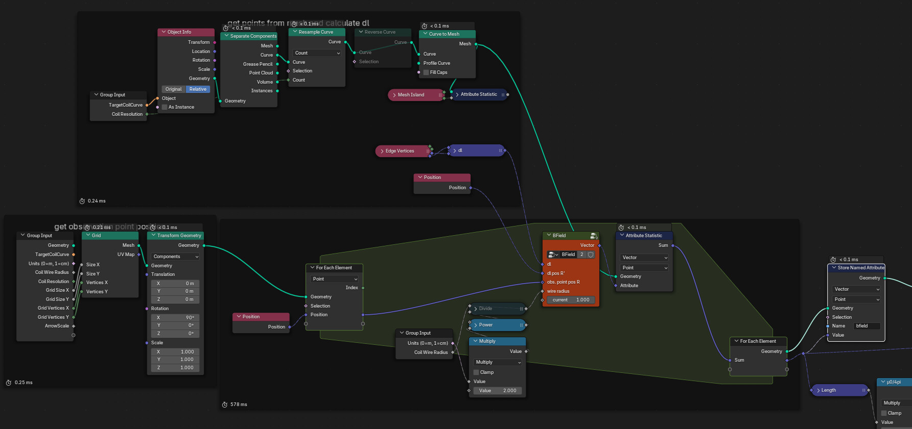
you are absolutely right, there was no need to use the Serparete Geometry node, and just writing the sum as a new attribute on the incoming geometry would suffice. I can confim now that the For Each Element zone does seem to be a lot faster than my first attempt and also faster than my implementation without the For Each Element zone.
See below a screenshot of my setuip and I have also updated the linked Blend file
I am now very excited about the For Each Element zone, and I will certainly be creating more advanced demos like this, I will also be tweeting about it. I really hope it does make it into Blender 4.3
Obviously these advanced physics simulations will always be slow compared to just pure code (python or C++), but my goal is to use the powerful procedural capability of geometry nodes to create a large number of models and designs, and then simulating them quickly to get initial results - perhaps not very accurate, and then aferwards picking a few potential designs and exporting them to a more advanced simulation tool.
And here is a video demo with using the For-Each-Element zone, I can increase the sample points, and make modifications to the coil geometry and see the magnetic changes instantaneously. I was able to do that before, but not with this much sample points.
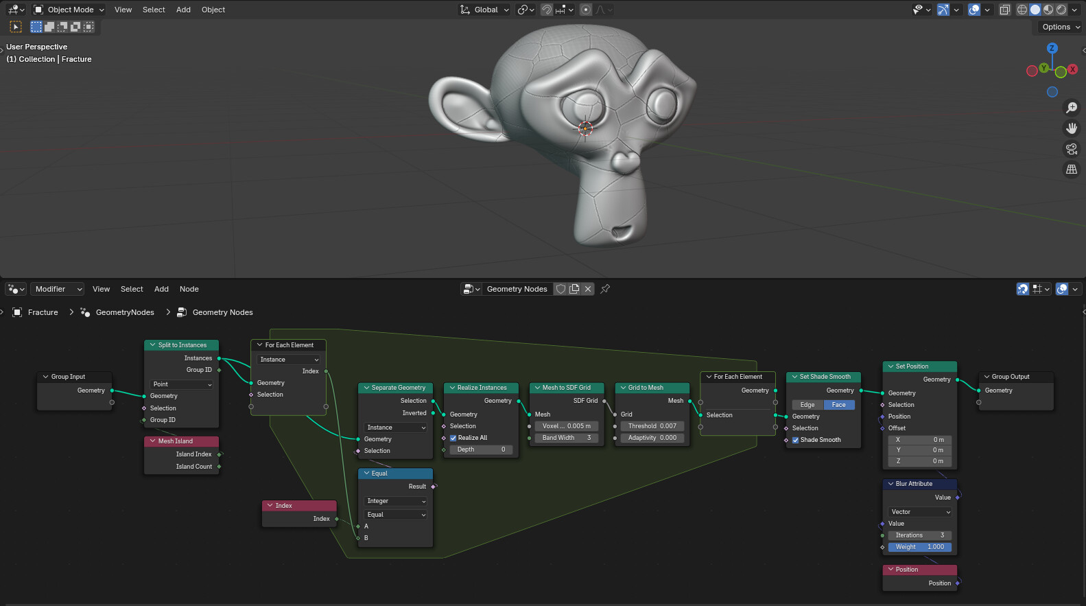
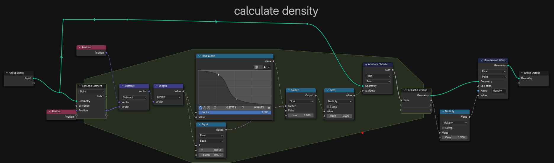
I’ve created a basic SPH fluid simulation using the for each element zone.
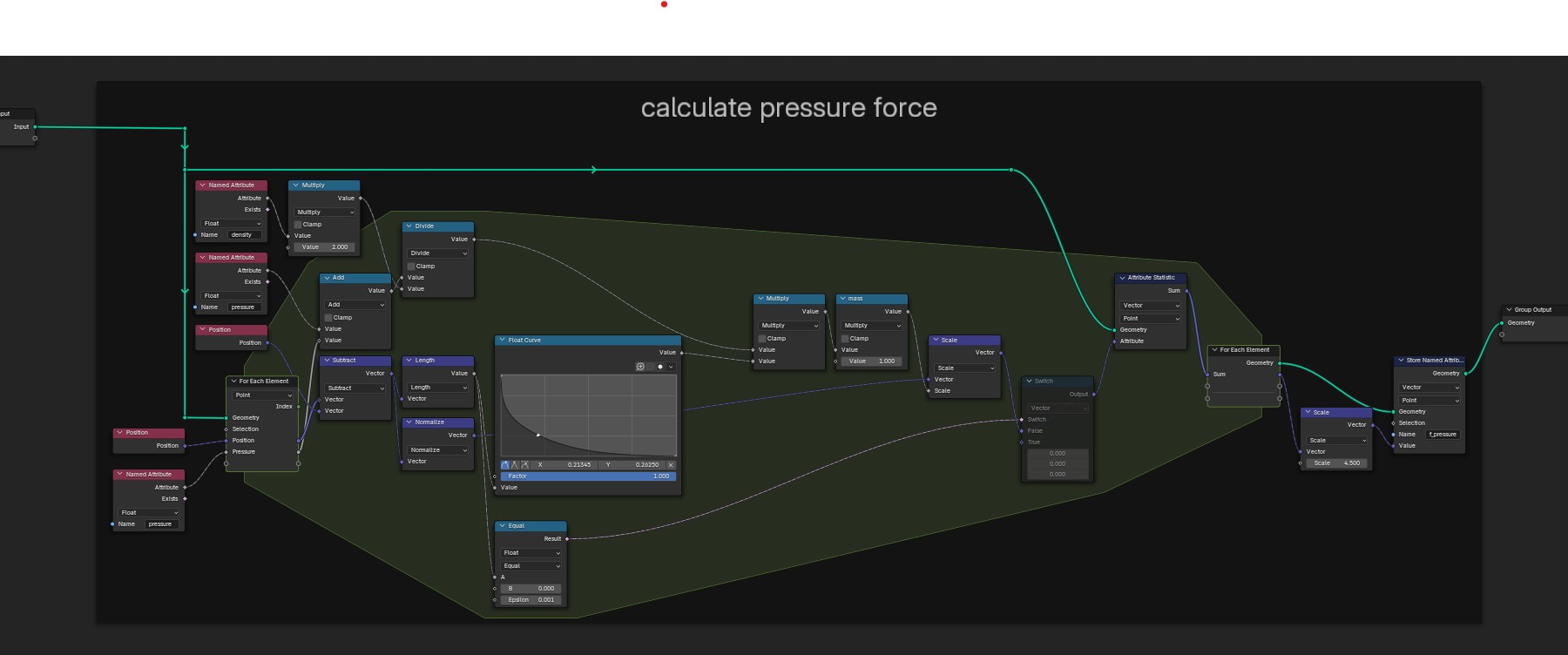
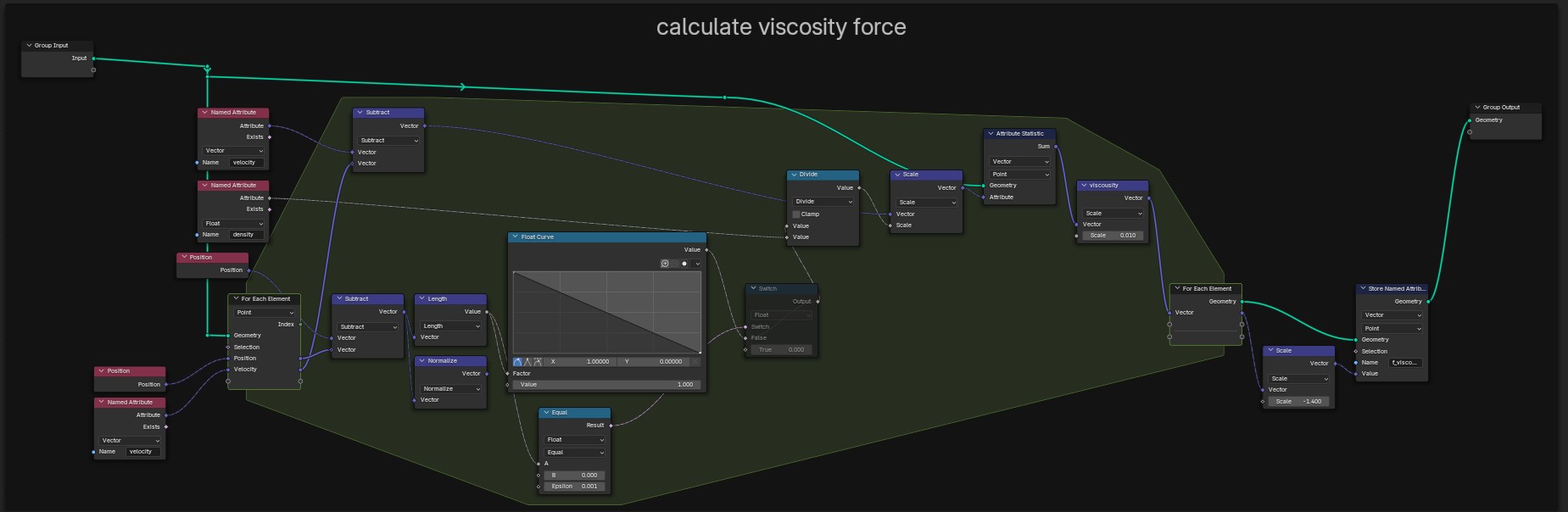
This simulation is based on Muller’s paper. I have three for each element zones. First calculates the density of the particels, second calculates the pressure forces, and third calculates the viscosity force.
I have not implemented surface tension force yet, viewport runs at approx 25-45 fps on my machine for particles up to 2000
Animation with 2000 particles and points to volumes
1100 particls - Low viscosity
1100 particles - Higher viscosity
This SPH simulation is only a demo, perhaps useful for educational purposes and benchmarking, I do not think it will ever be a proper fluid simulation solver.
You can download the Blend file here, you can adjust the viscosity force scale, it can get unstable if the pressure force is too high. Also I think there might be an issue with the boundary collisions, it seems particles are getting stuck to the boundary walls
How would I go about creating something like the Geometry Proximity node where there is a geometry input but the outputs are all dependent upon the context of the next geometry node? Is that not possible at this time? This truly can only operate on the geometry that is inside the zone?