made a small video - tried to follow your instructions:
Thnaks. That’s a bug in the modifier. I’ll fix. In the tool version, they are unlinked.
5 Likes
Is there any chance to have bevel go over the actual geometry?
I mean skipping the “clamp” limits and make the bevel bigger than what is possible now, as Bevel after boolean addon does (but in a destructive way)?
That would be a game changer imho. Also, if coupled with a join-vertex modifier, it could open new possibilities especially with imported meshes from nurbs applicatons.
What I’m thinking of is more or less what Cycles’ bevel node does, but with real geometry
1 Like
lsscpp: What you ask is #4 on my TODO list posted a while ago in this thread. It is possible, but quite hard.
6 Likes
Thank You very much Howard!
i just want to say thanks to the dev that work on the latest bevel update
So much time hav i expended moving edges manually, this arc miter is just too good. Thank you Howard.
3 Likes
kio: I committed a fix for the spread-tied-to-width bug in the modifier. Thanks again for telling me.
2 Likes
Arc,Sharp: When there is only 2 affected edges meeting with another edge at angle mitering is created and i think it shouldnt like in sharp mitering.
btw i’ve found some rare corner case for sharp inner
I’ve checked 2.79 and there it also fails :d. Its super rare cause i don’t recall if i encountered that before. Maybe its so rare its not worth investigating, has anyone encoutred this in production?
3 Likes
Love the new update @Howard_Trickey just amazing…

The area selected is something I solved but the right side is the original. It appears the arc puts a bit of stress on the center point which could be problematic with subdivision. Could it have a buffer loop in between to help with blending?
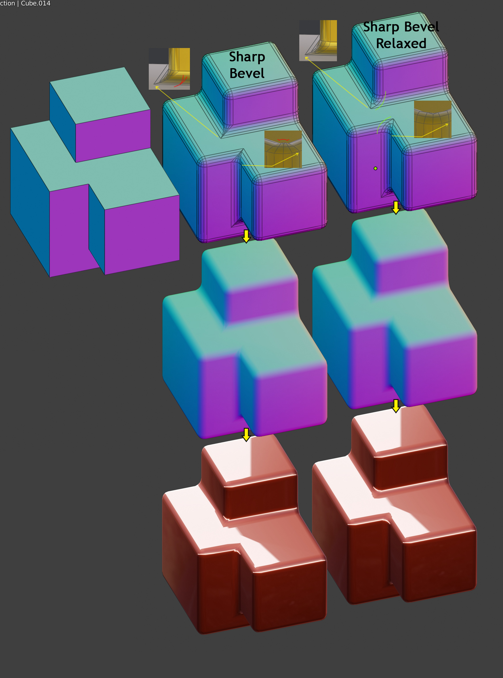
Hello Howard, the work you have done with the Miter Patterns seems incredible, even so I think that the original pattern has room for improvement if it relaxes a bit. I made some small rectifications by sliding some vertices towards the sides.
I think the image I upload is self-explanatory, any doubt I comment.
Thank you very much for your dedication, you are realizing the dream of many modelers.
2 Likes
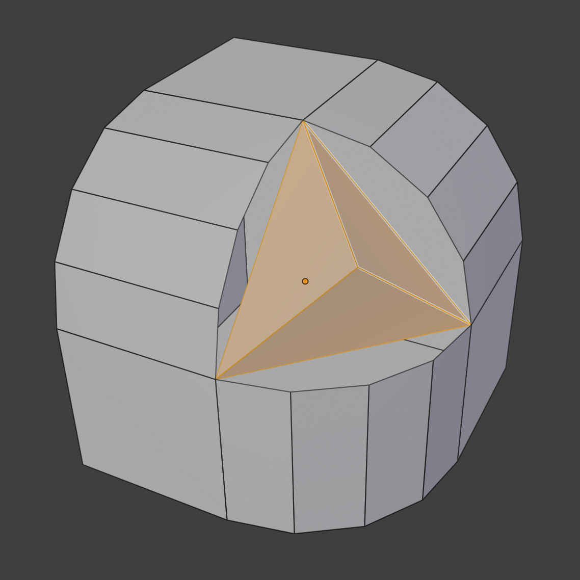
Lots of replies to address! I’ll get to them all eventually but first wanted to solicit ideas on what to do about the concave thing billrey saw on a case where inner arcs were enabled. I first need to give some background on how I generate the meshes that fill in corners where more than 2 beveled edges meet. Consider a cube corner with all three edges into it beveled. You get a hole like this that has to be filled by what I call ‘the vmesh’:
What people first think of is to use a kind of latitude/longitude pattern, like on the UV sphere. There is an easy math formula to say where the vmesh vertices go in that case. But that pattern isn’t so good because it picks out one special border vertex to get pinched triangles at it. People would usually rather have all quads, of fairly uniform size. So the general technique blender uses is to start with a pyramid that has as base all of the border vertices, like so:
(The position of the pyramid peak matters, and in face is a bit wrong right now - I’m working on fixing it.)
And then subdivide (like a Catmull-Clark subdivision surface, but with special rules at the border to keep that border aligned with the edges of the hole). In this case, after two subdivisions we get the familiar pattern:
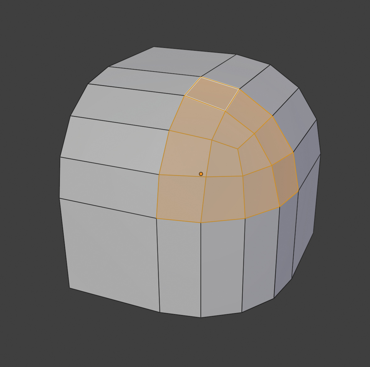
This works even when there are more than 3 beveled edges, and when the boundary vertices are not symmetrically arranged. And when the number of segments is not a power of 2, interpolation from the next higher power of 2 surface is used. And it generalizes to profile different from 0.5 (the circle case) by snapping to a superellipsoid.
But there is a problem: the subdivision surface generated by Catmull-Clark does not converge to s sphere surface. By setting the pyrmaid top carefully, one can come close but not exactly right. In the case of cube corners, or distorted versions of cube corners (that is, the angles can be different from 90 degrees), I can use a trick: after generating the subdivision surface, snap all the vertices on it to the sphere octant, like so:

(Matrix transforms can handle getting to and from an exact cube corner, if the original is distorted.)
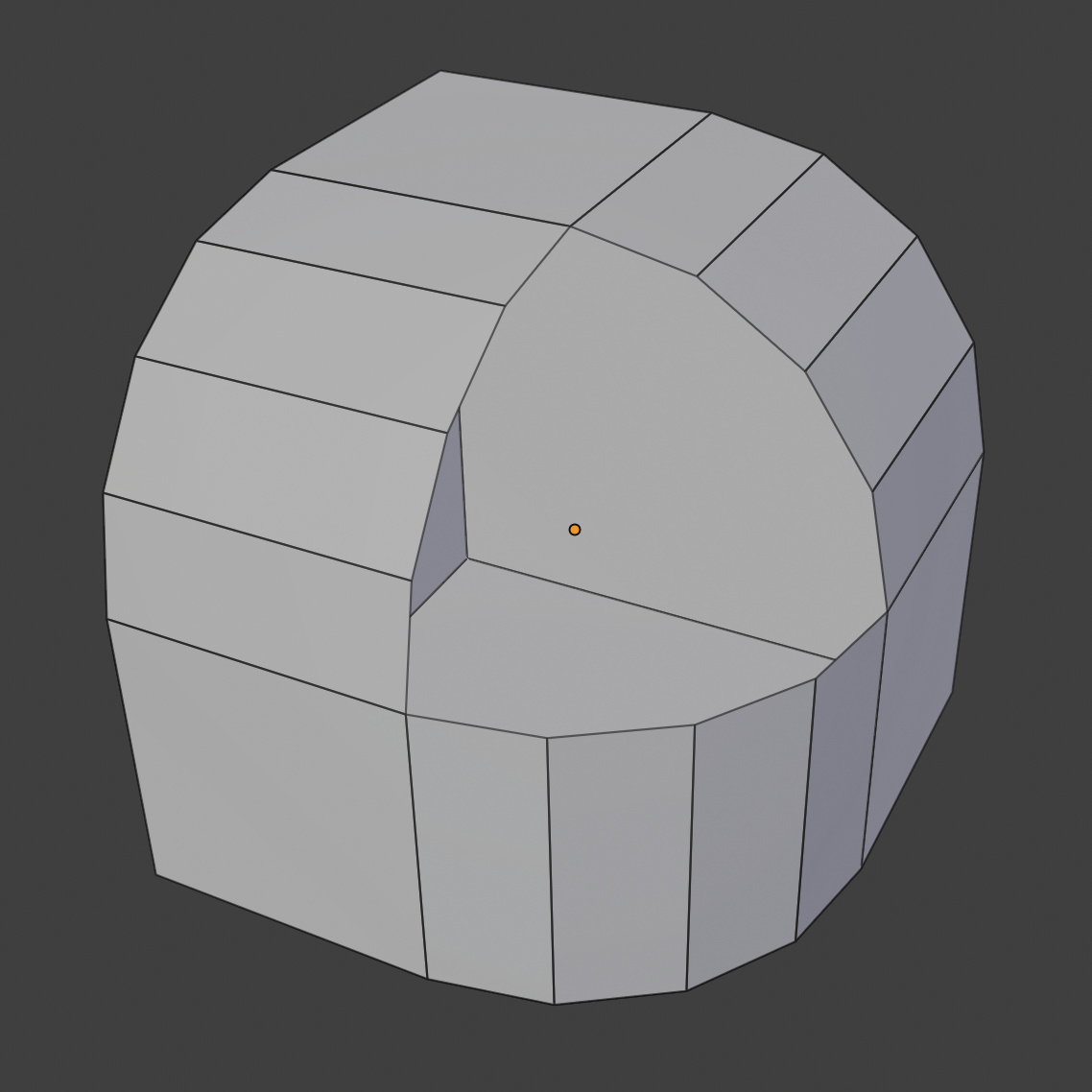
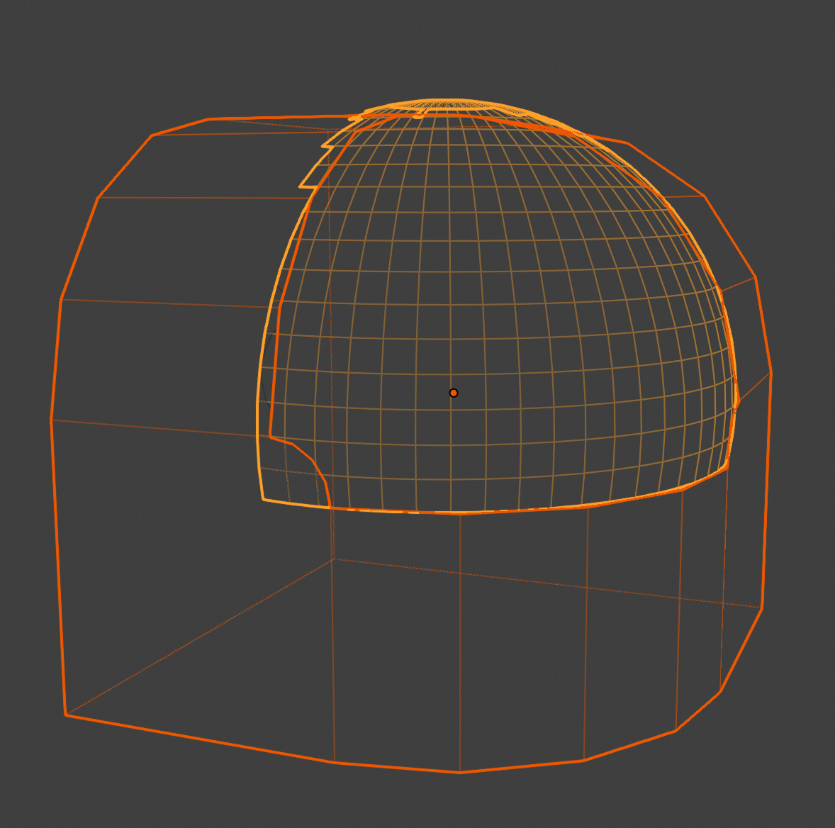
But now the problem that billrey noticed. When inner arc miters are used, the hole to fill is more complicated:
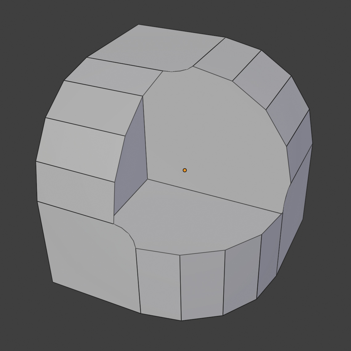
The subdivision method to fill the hole produces this:
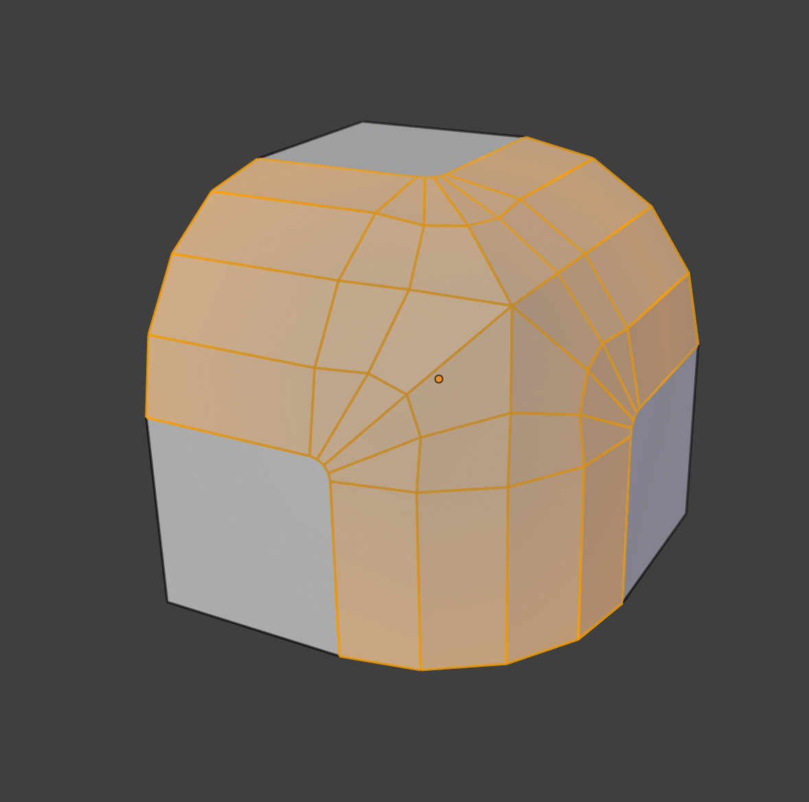
I thought at first I might be able to use the same trick, just snapping to a shifted bigger sphere:
But this doesn’t really work: at the corners, the sphere is just too big.
So I’m a little stuck, and am using the general subdivision method on cube corners with inner arc miters. I can play with the setting of the pyramid peak used to start the subdivision and that might improve things. But wondering if the other developers or the community has any other ideas?
8 Likes
This may or may not be an applicable idea, but I would think one way to solve it, would be to start by finding the limit surface for the bevel depending on the profile and width chosen by the user. Then, on top of that add your new beveled topology on that limit surface depending on the miter type and # of segments.
In other words, split the calculation of the mathematical shape from the calculation of the final geometry. Right now, the miter type seems to both change the shape and the topology. Could perhaps make it simpler this way?
Also, is there no open source library available somewhere that can be looked at for reference? This kind of mathy problem seems like the kind of thing one would think would be available in a paper somewhere.
The arc miter type in this case seems to basically use the equivalent of the following topology:
Beveled arc miter corners on. the left, OpenSubdiv on the right:
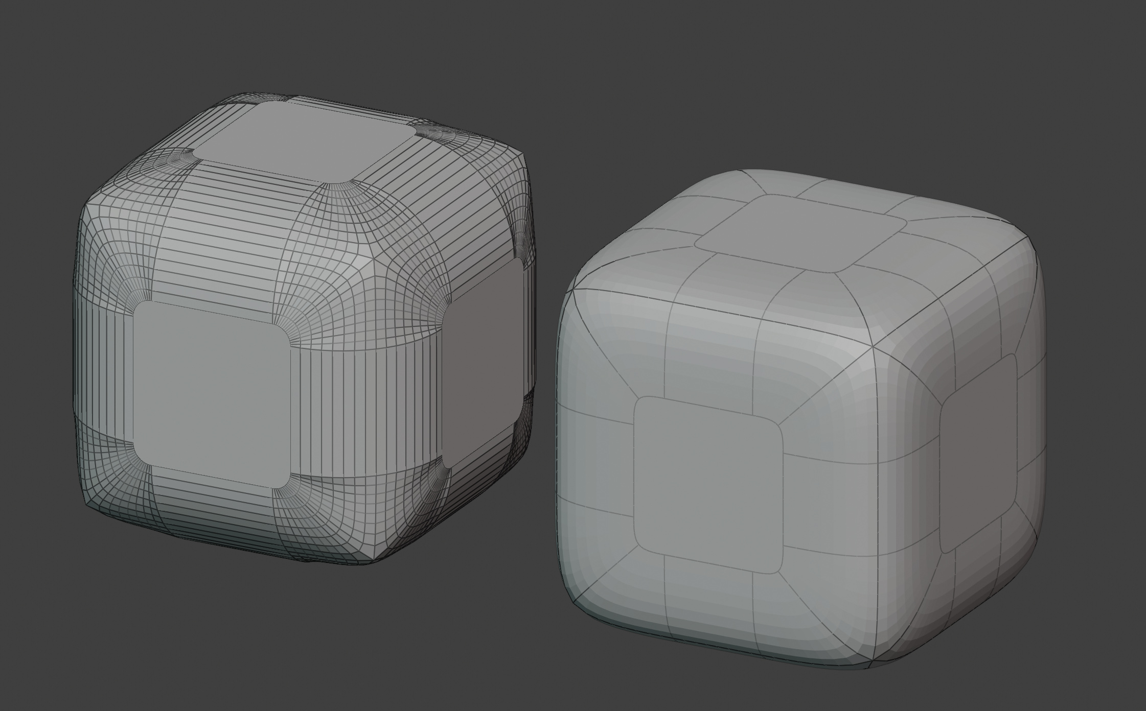
Could you make use of OpenSubdiv here even?
Again, here is Arc bevel left, OpenSubdiv right:
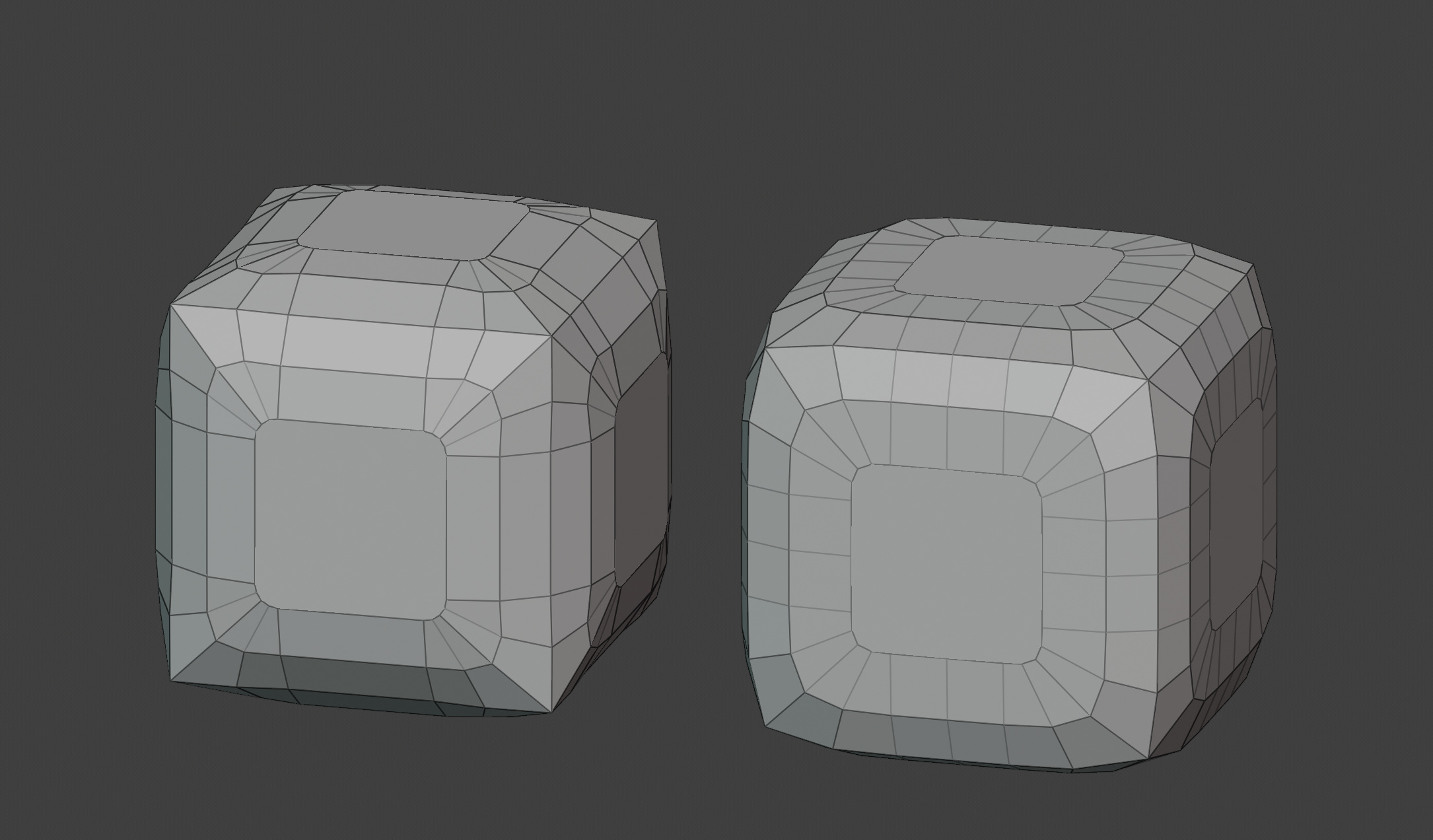
You can see how much smoother OpenSubdiv is here, which is why I wonder if it would be used?
1 Like
Hi, the new algorithms are great and are already a big improvements, it even may work better in some cases, but is there any posibility or has it been considered to have the chamfer to act as in max’s quad chamfer?
I use the techniques shown here (at 54:10), and I feel like it may be less polygons or cleaner/easier to model with it as it keeps the lines that are aligned with the axis straight, it also keeps the same width in the “L” intersection.

EDIT: Just checked maya’s and c4d’s bevel and I see where those other modes here came from, the “auto” or “none” modes in maya are better as the width like max but also curvature on the new vertex/vertices, in c4d you can even enable or disable this option

1 Like
billrey - thanks for the thoughts. It is possible that your two-stage idea could be made to work.
When I first programmed this, I could find no open-source code that did anything like it. There were some papers, which I kind of followed. E.g.,
Filling N-Sided Holes using Combined Subdivision Schemes, by Adi Levin
Your suggestion of looking at Open Subdivision, now that it is in Blender, might replace the custom subdivision code I wrote, is something I also wanted to look into. Your comparison picture isn’t exactly what I need since it curves the long edges too, but it is possible that the math in Open Subdivision is better worked out to make the curvatures smoother. I will look.
.
11 Likes
Howard, you are a skillful and resourceful person. Congratulations for the work you are doing for all of us. Thank you!
7 Likes
@Howard_Trickey Here’s an example of bevel’s profile ‘breaking’ (really just giving unexpected results) I saw on Polycount: https://polycount.com/discussion/comment/2668506/#Comment_2668506
Quad-based topology (which I’ve seen you discuss as being an option in the future?) would be a lot better here
@Howard_Trickey Amazing improvements… Thank you!
1 Like
@Howard_Trickey
Just to note that I agree fully with @billrey’s prioritised list.
One note: When you do add user profiles, please have them be part of the interface (as the brush curves currently are) and not actual 3d objects as is currently the case with "Taper Object’ and ‘Bevel Object’ on curves, as well as a few other places.
Oh thanks, I somehow missed that