I don’t know how it should work technically - something about angle spreading / limiting probably - I just pointing issue that may have solution or not 
The method right now when a single beveled edge terminates at a bunch of edges is to just make an ever-expanding polygon at that vertex, sliding each along the unbeveled edge. What you say it should be is just one of many other choices, where some of the unbeveled edges stick together and some don’t. How is one supposed to choose the best out of all of those large number of choices?
1 Like
Hi, it was bothering me since new miters were added. Bevel tool (in edit mode) has only 2 options for “inner miter”, but bevel modifier 3.
Bevel tool
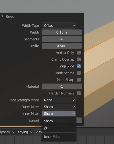
I was wondering did “patch” option got there by accident? because it seems it does the same thing as “arc” mitter and bevel tool doesn’t have it.
1 Like
I don’t understand very well the “not” in
…, it would be nice not to have the bevel modifier behave like a “real world tool” does.
I think the rendering should be as close as possible to reality, taking into account the tools to make the pieces.
Indeed, in my case, the details that can be show to a customer must match as much as possible to what will be manufactured.
So, for me, the beveltool isn’t realistic enough.
Off topic : I’m only a little Blender’s user that I do not master all the abilities. But when I draw a plan on DraftSight (AutoCAD like) with exact ribs and offset tool, with Blender, it’s more difficult. I remember the tutorial Modelling a 608 Bearing where it isn’t very easy to draw.
For instance, you have the scale tool but you have to calculate the ratio, and, for me, it will be simpler to give a exact offset distance than a ratio. Maybe a option “percent/mili-meter_or_inch”.
And I agree, it would be great if Blender had build-in CAD options or a add-on.
Sorry for my “translate.google” english. 
1 Like
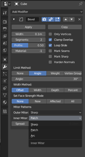
Way - you are right, there should not have been a Patch option for the inner miter in the Bevel modifier. The Patch option only makes sense for outer miters. I think I was just being lazy when implementing the modifier options list and used the same one for both the inner and outer miter options. I should fix this…
3 Likes
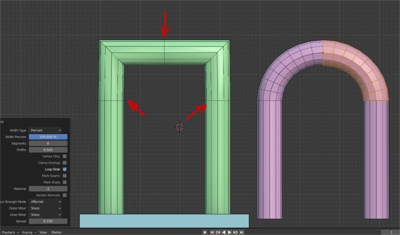
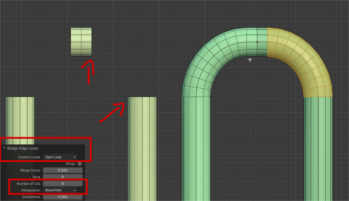
Something to help with that would be nice, luckily there are some work arrounds, like placing limit loops for bevel in percentage mode or using “Bridge Edge Tool”
2 Likes
I don’t think I understand what you are asking for. I guess you want the curved thing on the right of your pictures but what input do you want to give bevel (which edges on what model do you want to select and then have bevel produce the right side model)?
if its about my post i was just trowing some tips to get results (A) in other way, and i was preparing an example just to clarify that wasn’t something important but i just notice that bevel works different in plane surfaces or models with some volume.
(same modifier in both models)
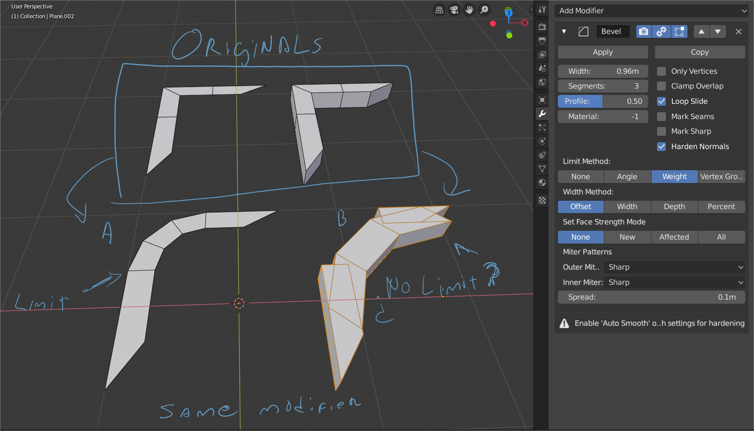
Im going to sleep now, later ill investigate this a bit more, probably its my that im sleepy and there is something im not seeing.
It is true that the 3d and 2d behavior of bevel is different. Originally, there was only 3d behavior. Users started asking for 2d things and I added them, but now that has led to the situation you have noticed.
One question to ask yourself: in 3d, which axis should one be looking down in order to apply the 2d behavior? It is undefined, I think. Maybe one could think of heuristic rules but it is not obvious to me what such rules should look like. I think I’d rather just have it that if you want 2d bevel behavior, do it in 2d, then extrude afterwards.
Not sure if this is useful or not, but this is how Modo handles it- which is interesting:
It looks like it takes the general ring direction and allows it to “overshoot” as a bulge rather than create geometry that crosses over itself.
Well, there is some interesting discussion going on at twitter, and especially this reply. What is your opinion on the best behaviour in this case?
Why is everyone mis-interpreting this clip? It’s about the materials bugging out!
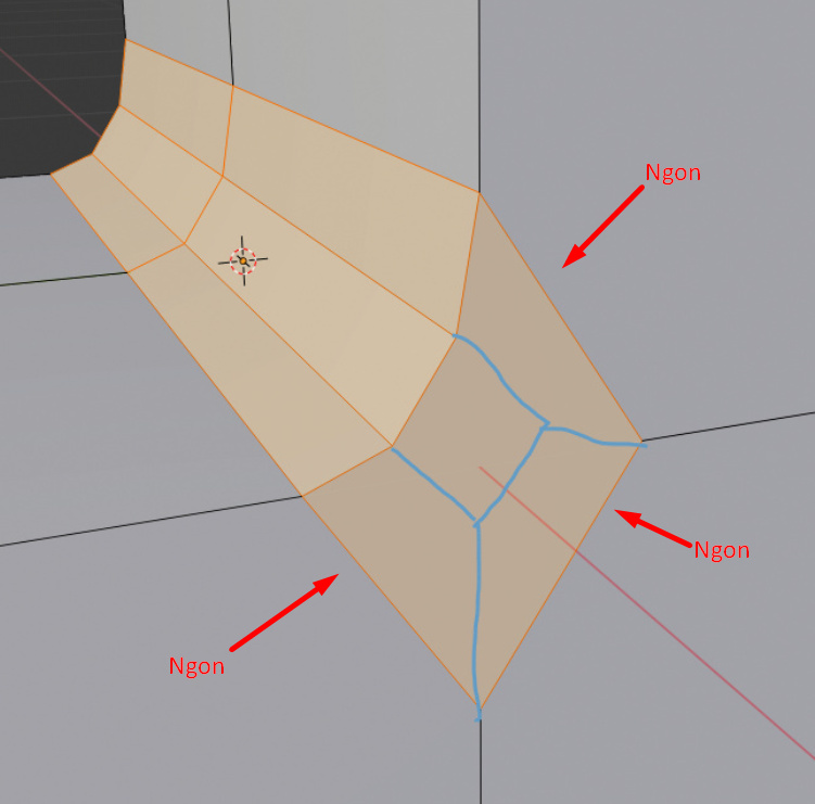
The bevel results in this situation seem fine to me. I honestly want the Ngon in the middle, not that mess of edges that we see in your second link.
3 Likes
Just wanted to chime in to drop this image (annotation tool in blue):
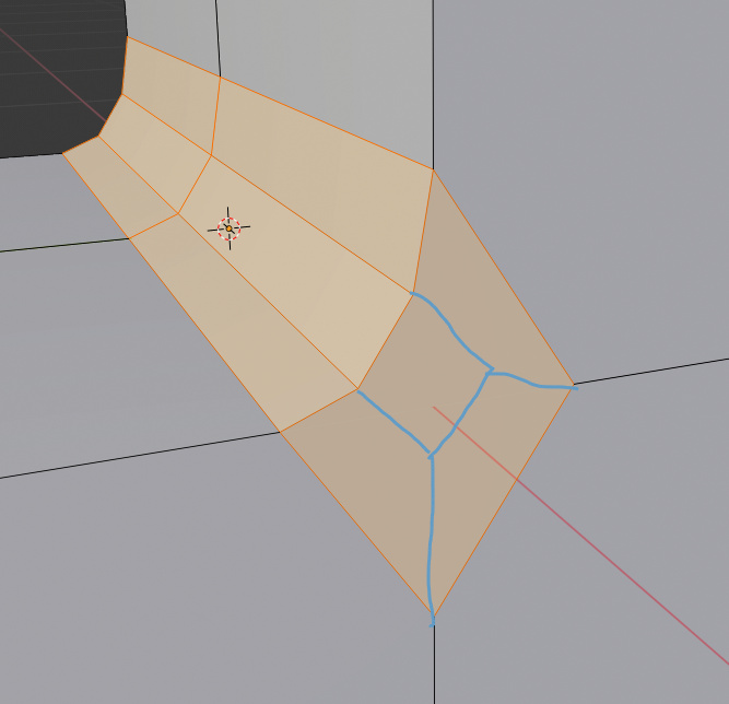
Could be great if the bevel tool could be able to generate this kind of patters automatically instead of ngons or triangles.
Cheers!
1 Like
Nope, the current behavior is ok, you don’t have too much to clean.
2 Likes
What?
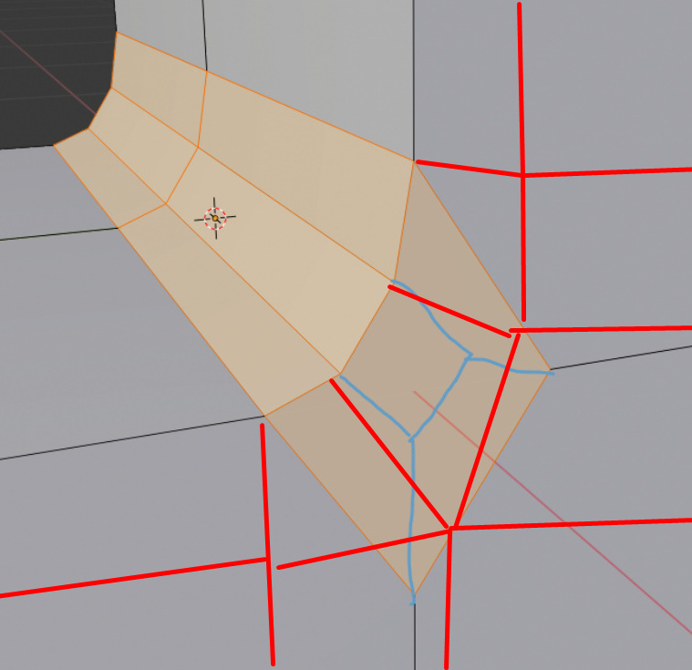
I prefer to have nothing to clean than having “not too much” to clean… current behavior don’t work directly with subdiv and don’t generate correct topology in similar cases, this would work, and if more subdivisions are done you have much more to clean.
I don’t understand your answer… is like saying “why do we need a knife tool if we can generate a vertex in the middle of the edges, connect it and move it, not too much work to do” 
Cheers
2 Likes
What you suggest is a bad result, you cannot keep that honnesly.
On both solution we need to remove all those edges and make a proper wire.
So, yes, I prefer have less work on the cleanning.
2 Likes
I disagree with that but I may be wrong, can you show what could be the correct topology in a similar case in your opinion?
Cheers
You cannot have a direct and correct result on this case, you need to edit the mesh.
So, less work to clean is better.
3 Likes
I just showed the bevel, but could be good to see what you propose as the correct topology in that case, the current solution is not good, it creates a big ngon, what would you thing could be the correct topology?
P.S.: just saw the drawing