I would certainly back up @Wazou proposal as I always use this option. Can’t say for newbies but it doesn’t seem to hard to figure out.
1 Like
I use Weighted most of the time so I’d disagree with switching it from None. Also I agree with Howard in that leaving it as None is kind of a neutral place for it. Changing it to Weighted or Angle feels more like changing it for a specific workflow, which I think we should avoid.
Bevel modal (and other modals) have this behavior of jumping after releasing Shift
I think it is bug and correct behavior should work like in wrapper like that:
shall i report this?
We have a task on phabricator about using correct units for things throughout Blender.
We have an issue with the bevel ‘Amount’ property, which prevents us from using real-world correct units.
The problem is that the property is shared and can be both a width or a percentage depending on the Amount Type property. We would need to split the Amount property, so we could use the correct units or each.

I had fixed that issue in the modifier (there are separate properties for amount and amount-percent, and the appropriate one is displayed in the property called ‘Width’ or ‘Width pct’). I forget why I decided not to update the “Amount Type” box in the tool the same way; I hope I was not just being lazy, but that was probably it,
The complaint above was about the modifier, where I believe the units are displayed correctly. The issue was not that the value wasn’t displayed with the proper units, but rather that he things the actual underlying default value to vary according to the units chosen. I.e., internally the default value is 0.1 blender units. When units is meters, this displays as 0.1m; when it is centimeters it displays as 10cm – both of these represent the same 0.1 blender units. Wazou would like the default to change to 1mm when units is centimeters, which would be .001 blender units.
3 Likes
Sometimes objects are not in 1,1,1 scale and the user may prefer to leave them like this. But in that case bevel modifier (as well as other ones) will use the scaling factor on the size of the bevel. Wouldn’t it be useful a checkbox “Ignore scale” or “World units” that counteracts the scale factor and so creates the bevel of the exact needed measure?
(the same question is valid for other modifiers, like solidify, array, etc…)
3 Likes
Zuorion - sorry, I don’t understand what you are trying to say. What are you using Shift for?
lsscpp - I started a discussion here recently on whether it was time to make all modifiers and tools not work on the original (pre-scaled) object, but rather the scaled one. The discussion kind of petered out, as there were arguments pro and con. And it’s a bunch of work to do it for all tools.
I have resisted requests for more and more options to bevel as it makes the interface more and more complicated (and internally it is already the operator with the most internal parameters). But I might consider adding an option as you suggest. Not highest on my priority list right now, however.
2 Likes
Personally I hope the discussion resumes for having tools work on the scaled version because I find it so odd and confusing that they don’t. I’d imagine many new users would feel the same way. I’ve been doing 3d art for 20 years now and even I had to do some research on why my bevels in Blender weren’t evenly scaled. Or hell, even if it was an option that could be set in the preferences (everyone loves options, right?)
1 Like
Not only is this technologically somewhat of a challenge, but it just pushed back the need to understand object scale. Considering all the other tools that won’t work as expected with non-even object scale, I don’t think there’s a good reason to include it here.
Not to derail the topic, but I have never needed to use an object’s scale in all of my years of modeling and it’s never been an issue for anyone I work with in any of the many programs we use. When I export out to a game engine I do need to be sure of the final size of the mesh but that’s overall dimensions, not that the engine cares if one side is 1.0 scale and another is 2.5. Perhaps for different mediums it is necessary, but not for all.
In modal bevel if You release Shift there is jump of amount value like you would never pushed shift But that minor issue (if at all).
https://i.imgur.com/kj8PzXZ.mp4
Great that you made modal keys configurable instead of hardcoded, thanks!
Could it be possible to have more property values settings and parameters for them during modals?
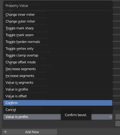
Like set profile to [parameter], so i could make eg. preset for profile (i press ‘X’ and its 0.5, i press ‘C’ and its 0.7 etc.)
or scroll changes segment amount, ctrl+scroll cycles through method, alt+scroll changes profile etc?
https://i.imgur.com/ddNOdD2.mp4
Also spread and loop slide is lacking in modal.
I absolutely love many of the changes to bevel so far. I came in here to post about the connecting edges for outer miter arcs, but billrey beat me to it, and the changes are already in and working great!
Sometimes I feel like I’m some weirdo who uses Segment: 2 Profile: 1.0 bevels and nobody else does. I have a minor suggestion for improving the outer miter, but I’m not sure if it’s viable to do, since it’s fairly specific to this case.
If that last edge were joined up in my gif, you would retain all quads. But this is specific to segments = 2, so I’m not sure how viable it is to implement.
EDIT: Kio’s post below suggests an easy solution to this, but reading further, I think that the extra edge for the sake of quads is likely to break curvature in many circumstances, and might not be desirable after all.
4 Likes
I think this would only be possible with an extra ‘quadify’ or ‘connect’ modifier. Which, to be clear: I would really love to see!
1 Like
One thing I would love on the bevel is a merge option, or a merge modifier.
3 Likes
that (remove doubles) would be really useful, and it could live along edgesplit
1 Like
you can force that topology by adding an extra edge like this:
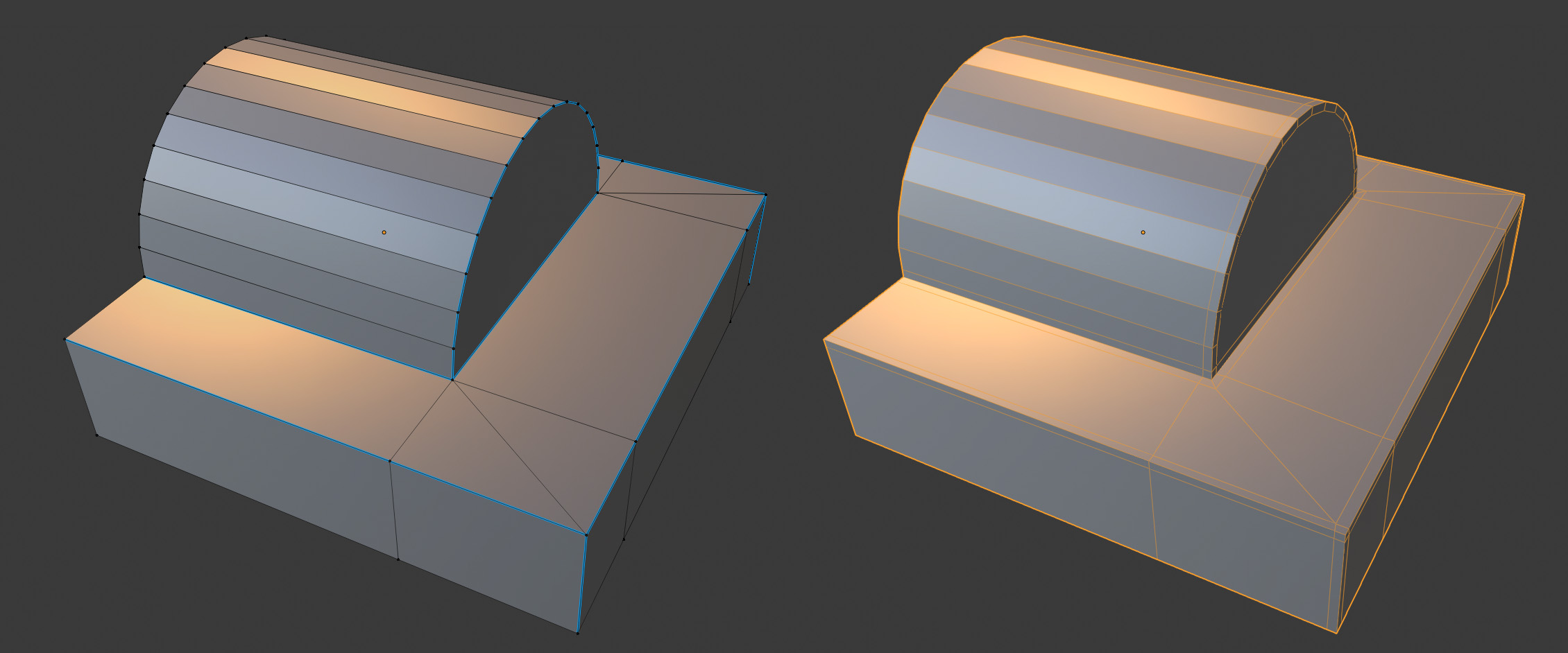
I wanted to give some more points to discuss about the bevel modifier in regards to subdivision surfaces modelling. For this I grabbed some random mesh from work which shows some of the issues we encounter regularily. Think of some bent hard surface model, with clean shading and uniform edge quality - just to give some contrast to the 90° planar technical models some people also do.
The original mesh was created in max with quad chamfer, but as it does not create perfect topology in all cases either it has been a bit optimized for better shading.
I took said mesh and removed the control loops, and added weights for for bevel modifier in blender to see how it turns out. It does not match 100% but i think its close enought to see some points. ![]()
I used arc for outer miter and sharp for inner, 1.0 profile with 2 segments and a subsurface modifier with 2 subdivisions.
Case 1:
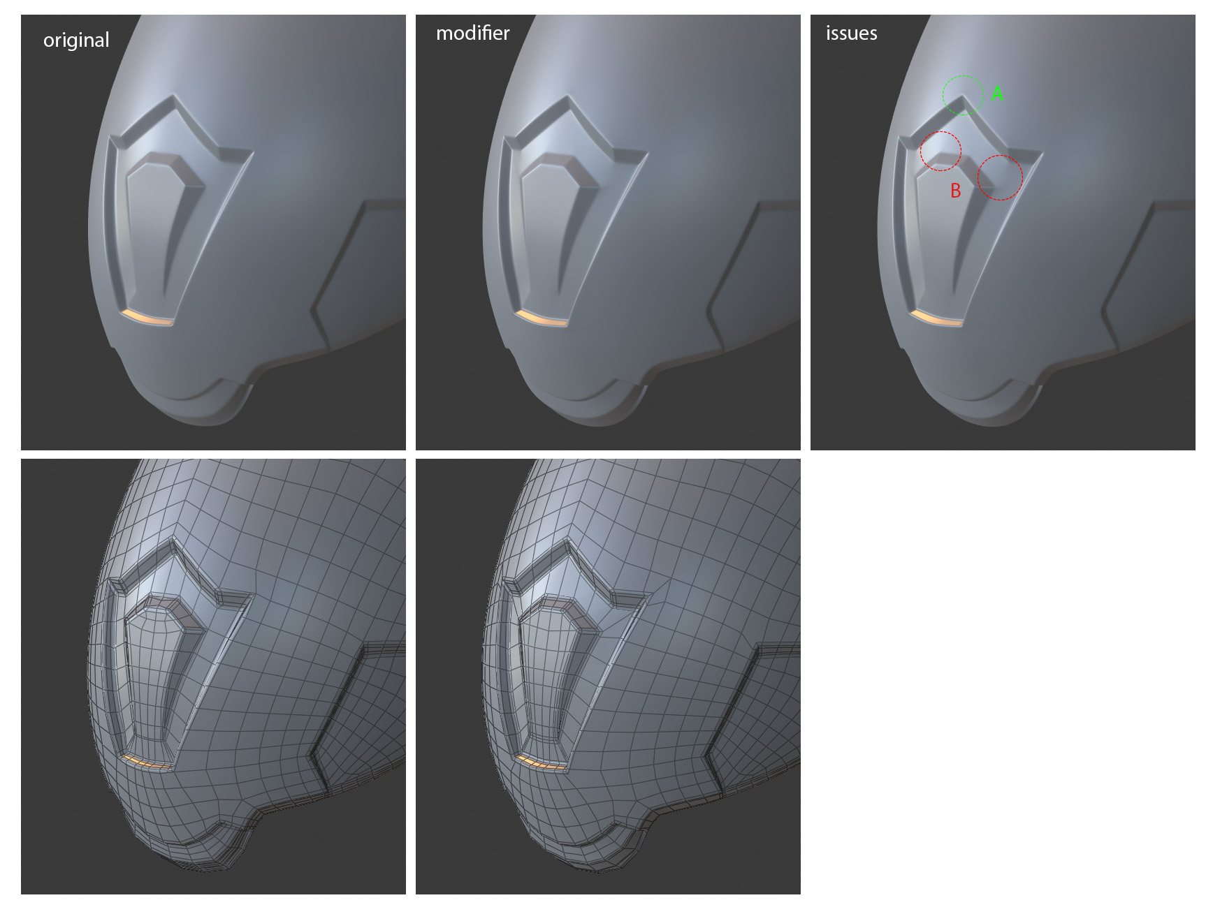
Over all its pretty close, but looking closer there appear some shading issues at the outer corners of the inset part. Arc mitter works great on A, but it does not really work on B - the surface gets bulgy because it adds quite some open edges. The original uses sharp miter here which shade just fine.
Case 2:
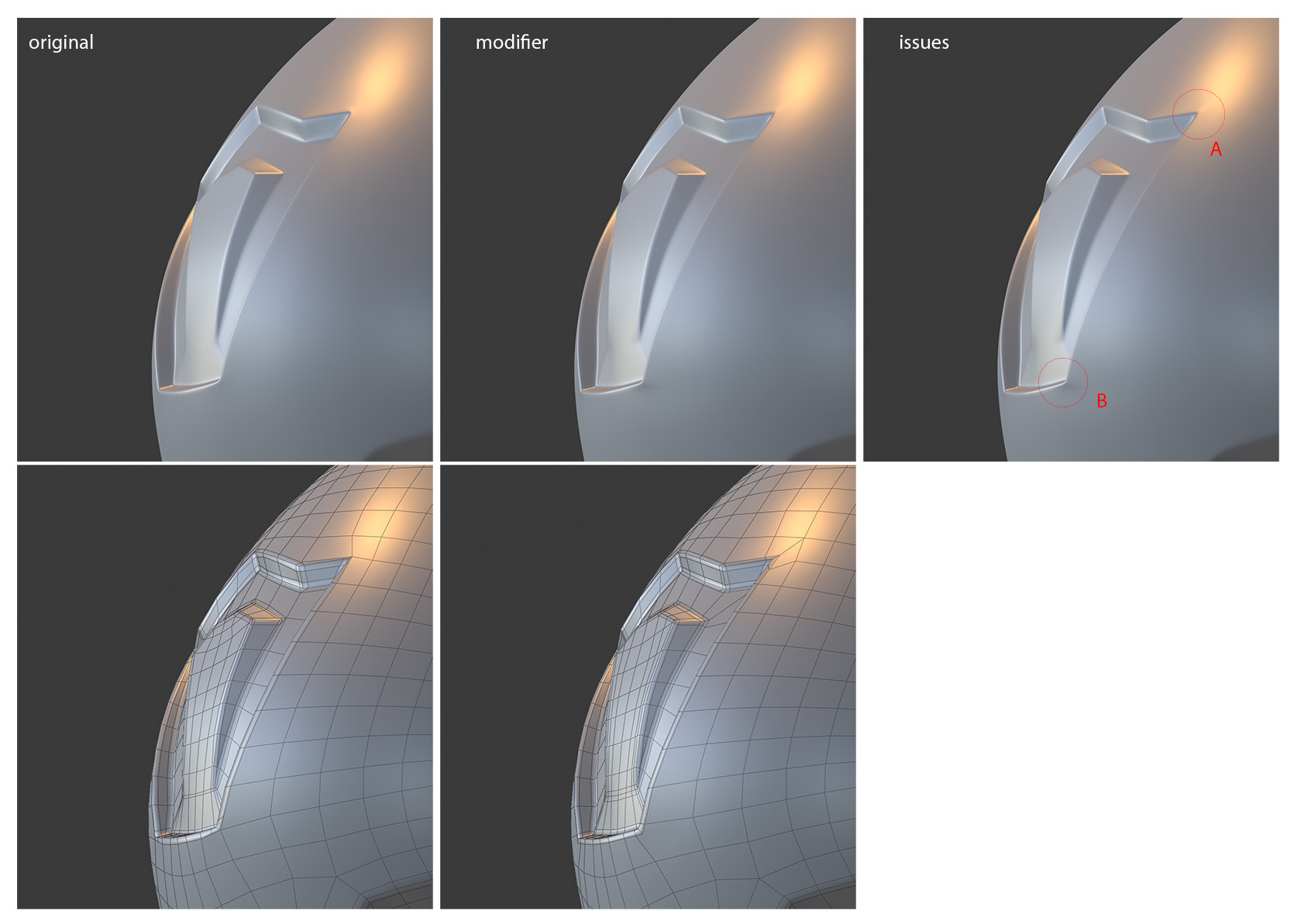
Here we see two outer miter corners, while A kinda works the shading in B is really not nice. Even if I force the same topology as seen on A onto B its not as great as the original.
So the gist of it is, that it seems like it might be worth a second thought if it should be possible to define miter type per edge somehow. I dont know if this is technically feasible or even implementable without spending too much hours…
thanks for reading.
4 Likes
Zuorion - OK, I understand what you mean but he Shift jump. I had forgotten the Shift key handling in modal bevel, as I don’t use it myself, even though I coded this a long time ago. It’s tricky to get the code right to handle transitions between the different value modes, and I seem to have a bug here.
Yes, I should add spread and loop slide to things that you can control with keys.
As to the property values settings and parameters for keymap - I’m not sure how to do that right now.
Rekov and michealknubben - yeah, some kind of ‘keep quads after bevel’ has been an oft-requested feature. In the example you show, that connection edge makes sense if the original face there was a nice convex quad, but maybe not in other cases. Anyway, such things could be added but it is a bunch more programming and there are other things on my TODO list (see earlier in this long thread).
Wazou: the next major thing that I will do to Bevel is make it merge properly. This is a long, hard task. (People might be interested in the “Inset Straight Skeleton” addon, used to be “Inset Polygon” addon, that I just ported to 2.8. It does collisions and merging, but only works on planar or near planar faces or groups of faces. And it doesn’t quite work in all cases – the special cases get very hairy here.) But will likely do better Booleans before tackling this work on Bevel, as Booleans are more urgently sort-of-broken right now (since Carve went away).
kio: Interesting examples; thanks for writing them up. I feel a little lost about what to do about it, though. I must admit that while I added these new mitering options because people said that they were better for subdivision, I was not really sure why. And your examples show that it is not necessarily the case. There is some subtle art/math involved in figuring out what geometry is going to yield the desired subd results, and I am far from understanding that.
As you suspect, it would not be easy to allow per-edge miter choices. The problem is almost entirely a UI problem, however – internally, the code could handle it just fine. And while I could probably figure out a UI to allow this spec on a per-edge basis for the Bevel Tool, the real problem comes with how to specify it for the modifier. I’m open to ideas here. But again, this is not going to be on the top of my TODO list, probably.
Another approach would be to try to figure out an “auto” mode for choosing the miter type. If there’s some rule we could figure out about when one type of miter would be better than another, then it would be easy to implement such a rule in the modifier and tool. But I have no idea what such a rule would be. Your examples in this post show that it is not easy, because I don’t see what the differing feature is between cases where we got good results vs cases where we got bulges. Any reader of this thread have any ideas here?
5 Likes
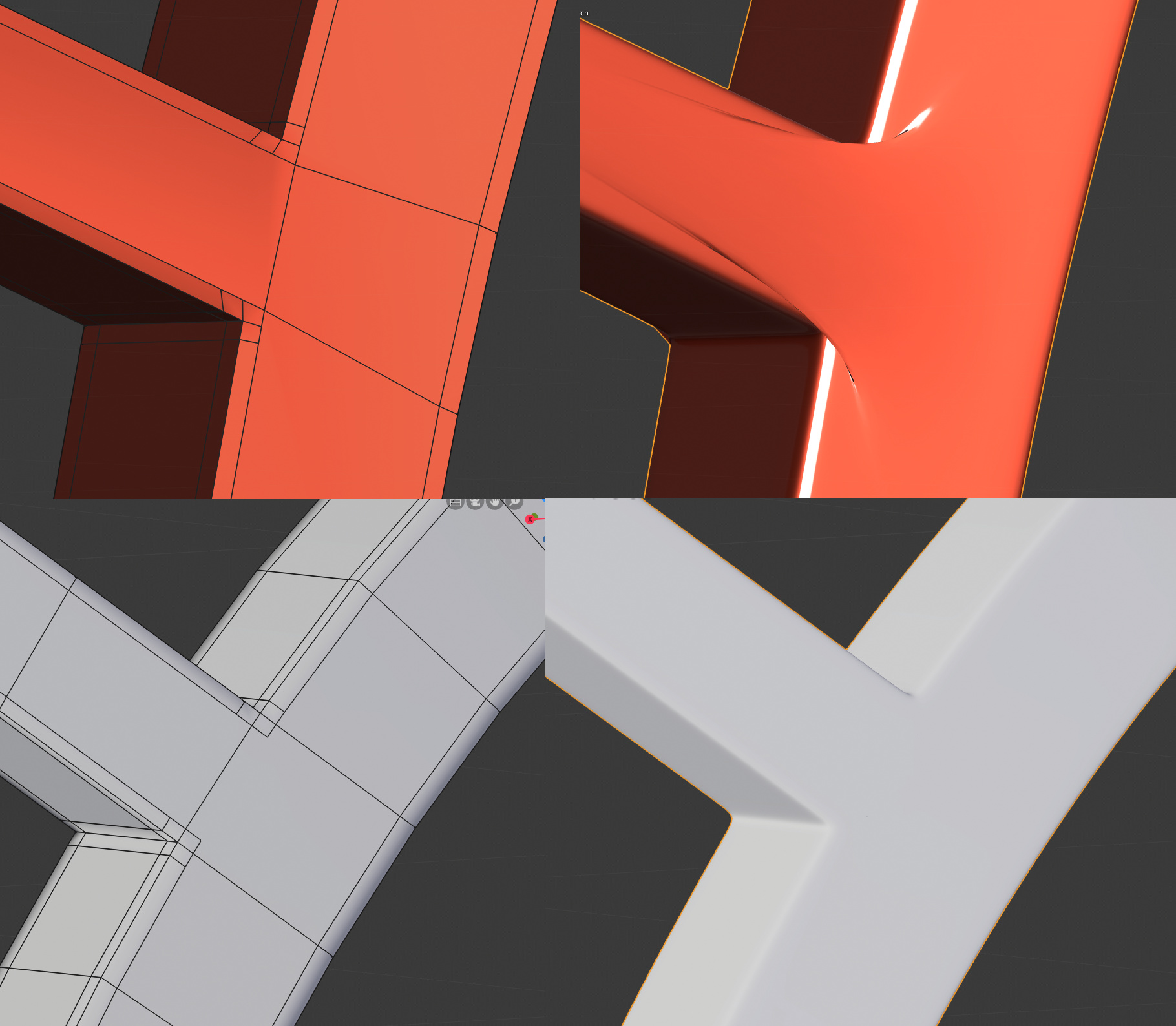
Howard T - The mitering options are definitely an improvement for subdivision surface, and one example of where you can see this is this bug I reported a while back. The outer miter option seems to have solved this issue when set to arc. I made a little gif to demo the results. Bevel by weight with Profile 1.0 and 2 Segments.
Unfortunately, I don’t think the current patch miter geometry is ideal. In the picture below, the red ones are the result of setting the outer miter to patch. The grey is what I did by hand, and the latter mesh still yields the best result over all, also better than outer miter: arc.
2 Likes
We need a triangulate on Ngons ^^
3 Likes
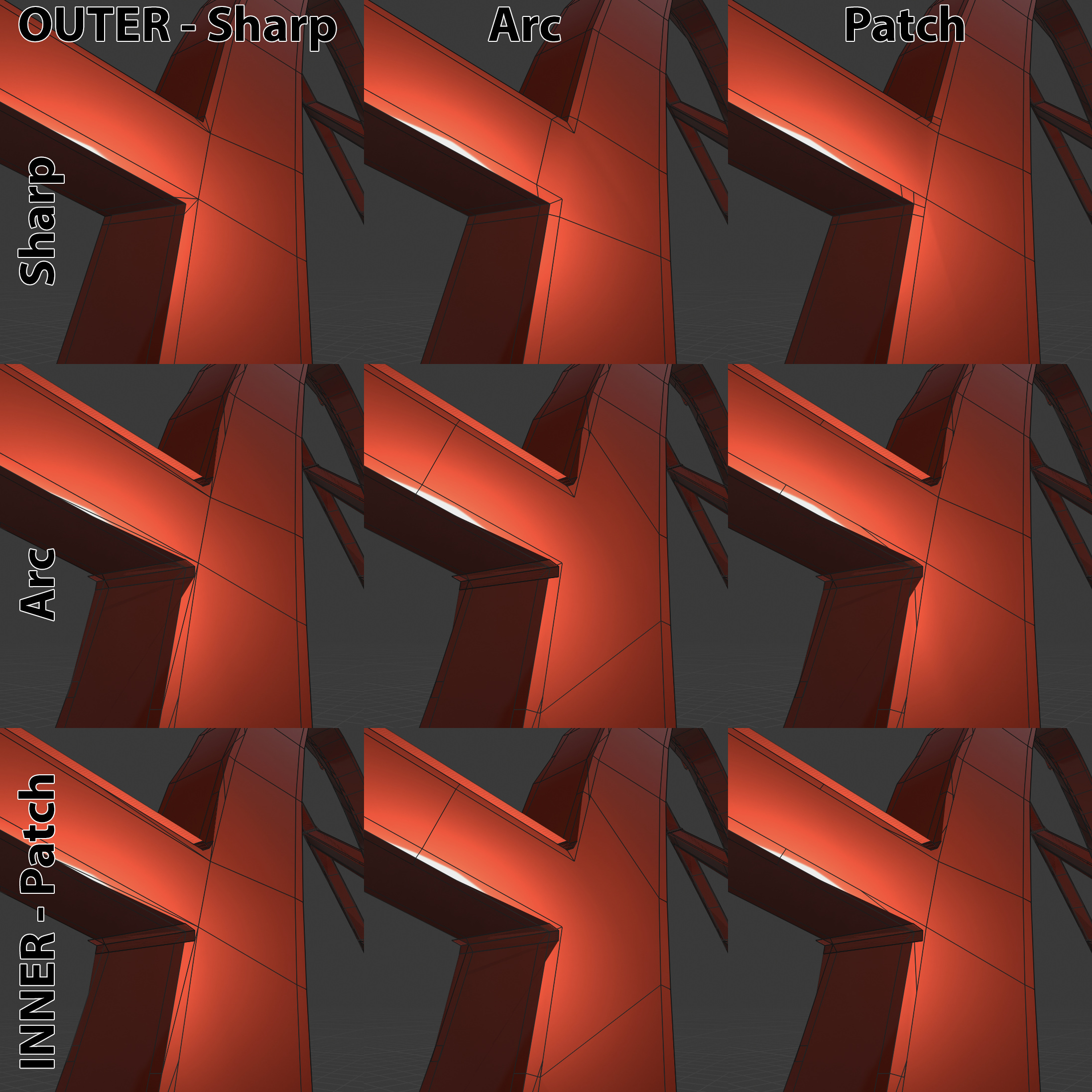
I also ran through all of the miter combinations in the somewhat unique Profile 1.0 case. As you can see, none of the Inner Miter options other than ‘Sharp’ produce useful results. If you are specifically interested in using bevels to create supporting geometry for subdivision, only Outer: Arc, Inner: Sharp currently produces a useful result.
I would just add that Outer: Patch, Inner: Sharp could produce a useful result if it were changed to match the example I posted just above.
2 Likes