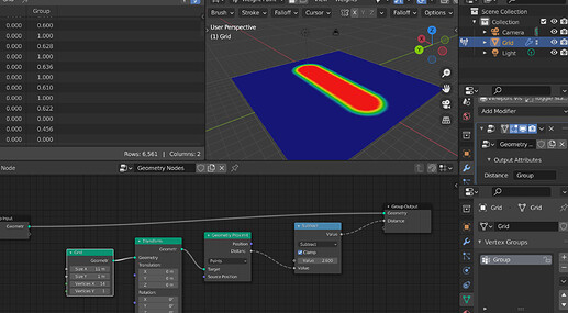
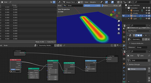
Sure, I was just wondering if there’s some conversation thread which I could get more info from. Nevermind.
I have really tried to get used to them over the last few days, but working with node networks with the dashed lines just does something strange to your perception of the node connections. Maybe it is just me, but it messes with your perception of the graph flow after a few hours of staring at them, especially on a complex network. Which is the opposite of their intention.
It is one thing to see a screenshot with the dashed connections, but when you start working with them you will really see that they are a bad idea. Just dragging them out from one node to another over a long distance or moving multiple nodes and seeing the dashes wiggle around and contort is disconcerting. I think there is a good reason why the commercial node based packages don’t use dashed node connections 
Hi,
reading the values in the spreadsheet was good for debugging though. It’s also useful to save attributes and use them later, to avoid making a spaghetti monster out of the graph and keep things organized.
Is there a reason not have both? Why can’t the Attribute Capture node have a name field to store it? Is it to avoid name conflicts?
It was also very powerful to store and manipulate existent maps, such as colormaps or weightmaps and pass it on for the rest of the software. As @Eary mentioned in the Fields feedback there is proposal for storing named attributes, is this planned for 3.0? The system would lose a lot of power otherwise…
Edit:
For those who’re interested, Hans clarified that the funcionality of editing maps with the nodes won’t be lost, and the viewer node will be able to view field values.
So how would I create a custom attribute on an object and then “Capture” it in another object via Object Info node?
On a related note, are there docs / task anywhere which list the built-in attribute names for each object type?
I’m wondering if there are any attributes on Cameras that I could access by name (Focal Length, Aperture, etc)
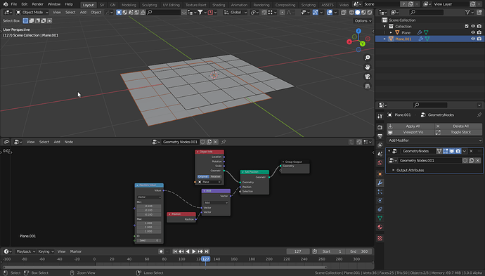
Dotted lines are unusual to my eyes, they also add visual detail.
It would be nice if dotted lines do not change frequency when node editor is zoomed.
Some ideas to soften dotted lines …
- decrease frequency. Longer periode.
- totally transparent gap creates strong contrast. It would soften the gap if lower opacity color (or another calculated color using theme colors?) is used instead.
- wider gap
If all 3 are applied, it could be something like …
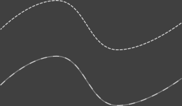
That looks better. Although I still think that color and line thickness is a better way to distinguish between different data flows. And if those settings are exposed in the theme editor, then they could be adapted to work with any theme. Then even dashed lines could be an option.
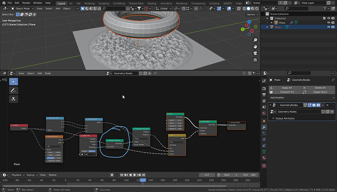
Object info in fields doesn’t seem fully operational in alpha master, when I try to change anything with position randomization for example it’s like it gives completely different results than the original geometry entry. I’m asking cause in recent list devs typed “No changes necessary”, but I gues it needs some changes since it doesn’t work? Or I’m missing something here?
The object info node outputs an instance. Until recently, instances were realized implicitly by all nodes, so that fact wasn’t so visible.
Here, the position of the instance is being randomized. If you want to randomize the location of every vertex, you need real geometry. You can use the “Realize Instances” node to get that.
Oh, I assumed that realize instances is more for plural use case, didn’t think that single geometry is instance now, thank you for clarification.
Is there a plan to improve the node is it prevents all the mesh data (UV maps, Vertex Colors / Groups, …)? This would be very useful for anyone who wants to export the GNodes output to a game for example.
Make Instances Real can do that, but it can’t be used for higher count of instances.
Thank you
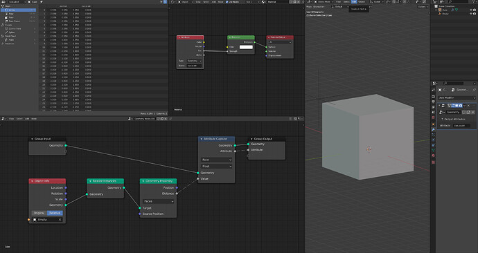
does proximity field works ? couldnt get it to work, it outputs a single vector only
It was not really a proposal, I am sure it is being worked on.
https://developer.blender.org/D12685
Thank you for the response, but i still can’t get it to work :
1- the attribute is showing in the vertex data even tho i have it passing through face like you did
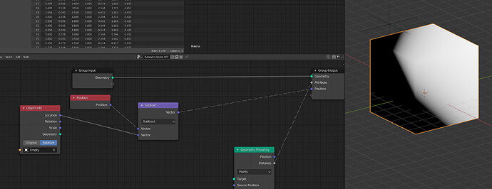
2- don’t we need to put position in the ’ source position ’ in the proximity node ?
I get a lot of crashes when it’s linked this way, for example if i move the empty blender will crash
That seems inconsistent, as the Mesh Primitives do not require realize instances.
It generally seems unintuitive to treat a single object as an instance as a default.
it kinda resemble the ‘packing’ of the big H, when you have to ‘unpack’ to access data, but yeah it feels counter intuitive
I don’t think “Empty” has any geometry, let alone faces. I would use the primitive nodes usually
Or if you really need to use “Empty”, you can do this:
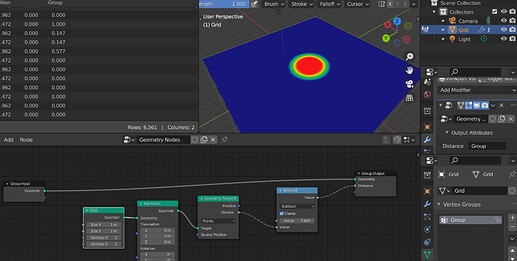
actually i wanted to have a gradient and i just remembered that i need to subtract the position of vertices with the location of empty
But thanks for your help, it helped me understand the new system better
EDIT: I turned out being wrong, see Geometry Nodes - #1978 by HooglyBoogly
It makes sense if you think of it, it treats geometries from other objects as instances.Because, what if that object is a curve object while your object with GN is a mesh? There can be different kinds of geometries coming from object info, it only makes sense to get them through the instance system.
And previously with the Explicit Instancing proposal we agreed that the users should be able to make instance real manually instead of guessing which nodes would secretly make instances real without the user’s knowing. Therefore this behavior. I think it makes sense.
It makes sense for the Instance on Points node to create instances, not for the Object node imho.
If the object is a curve, then the node would output a curve just like making a curve primitive. Isn’t that possible?
