This is the way ![]()
1 Like
Or a “sanitize normals” for when your colleague deals you a sketchy free model from the deep web and it’s completely messed up… like the lost in translation kind, scrambled by the times past
@LudvikKoutny It’s always been. I would like to see a proper control panel for socket management. Enums and expanded enums would be really cool also, to go deeper in the whole “procedural asset” fantasy…
1 Like
Socket type changing improvement is actually in the works: https://developer.blender.org/D10912
3 Likes
I am very curious what this ray cast node is for, any explaination?
https://developer.blender.org/T88078
Will we be able to use it to detect the distance (or more like relative position) between a certain vertex on object A and a certain vertex on object B? Or is it for something else? If no, is there any current solution for detecting this distance? This would be useful for like rolling ball animation on bumpy landscape.
BTW, how do I rotate the object in world space with transform node? EDIT: Nevermind, my confusion, it is already world space by default
Ah yes, I recently ran into this when doing a recent Youtube tutorial! I needed a float parameter going into a vector input and realised that I needed a dummy math node in between. Certainly made the tutorial explanation a bit more awkward than it needed to be 
It casts a ray from a point(s) based on direction vector and returns hit location(and some other attributes) where ray hits a face. You can stick instances to a terrain for example.
4 Likes
Oh perfect. I hope this will be committed ASAP.
Thanks for explaining. It sounds indeed like what I expected. It will be nice to use it for my rolling stone animation
1 Like
Raycast node ? I love this. Don’t you folks try to make a renderer out of that. A geometry nodes renderer… we’ve gone too far
Nothing will ever beat using Postscript to make a printer output a raytraced image 
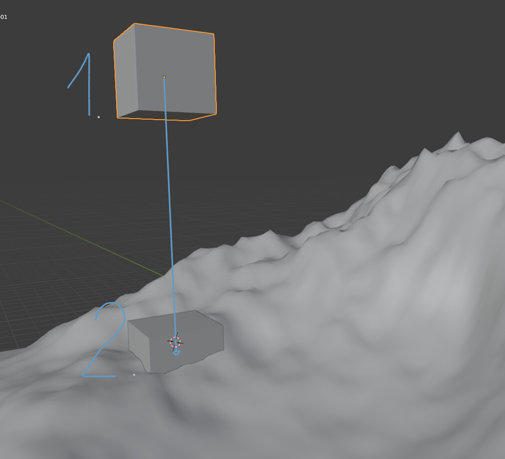
I’m trying to recreate this:
This is how far I’ve gotten:
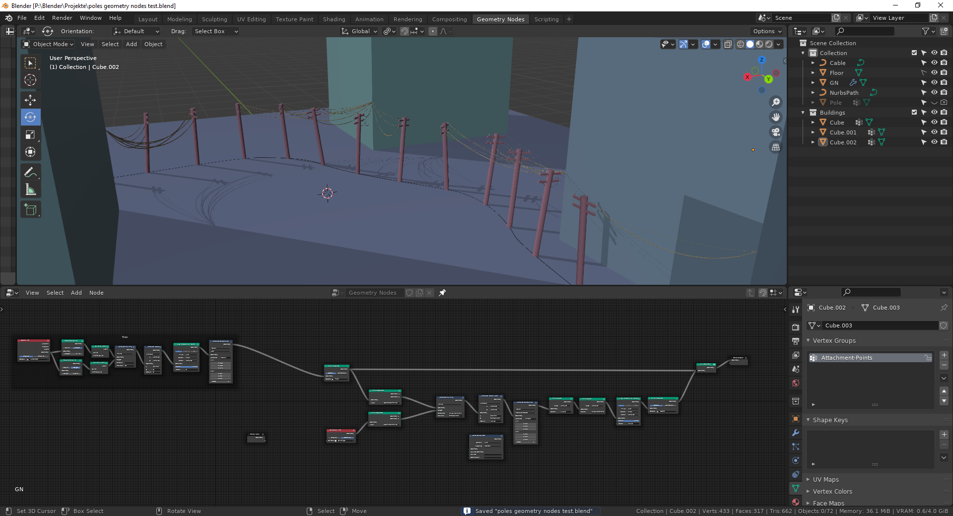
Now the problem I’ve been running into is that I can’t connect the poles with each other.
For that I’d need the Attribute Proximity Node to return the nearest point that is not itself. Is that or a more general return the 2nd closest point planned?
Obviously Jesse has been able to do it without that feature, but I can’t figure out how ![]()
Attached is my file, just remove the .txt from the file extension
poles geometry nodes test.blend.txt (168.0 KB)
4 Likes
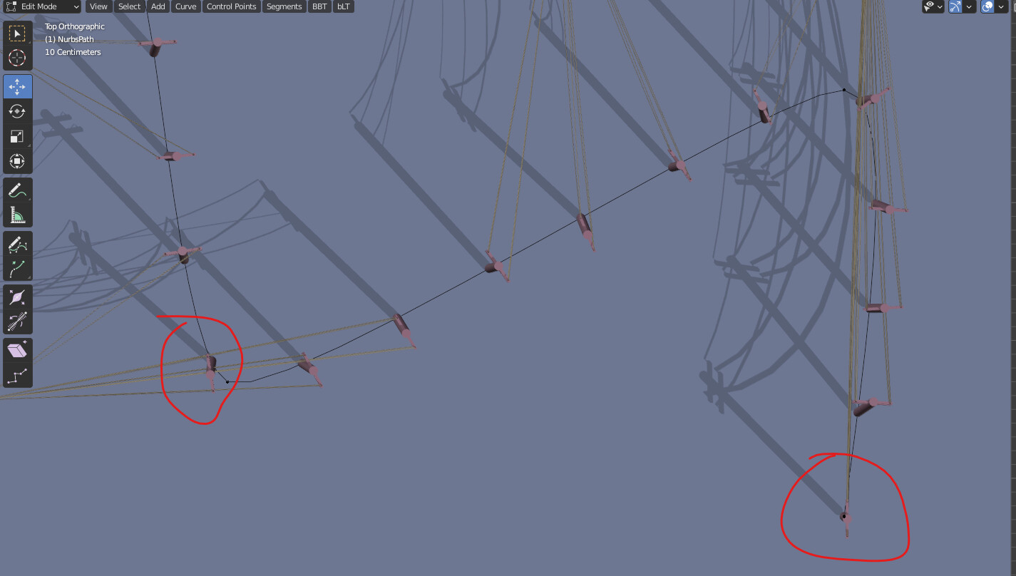
Nice job so far. Not sure if you’re aware, but some of the poles don’t follow direction of the spline.
Only the first doesn’t follow, the others might look a bit off, because I’m randomising the rotation.
I’m calculating the vertex normals by sampling two different sets of points on the same curve and then using the attribute proximity node to get vectors pointing along the spline. Since the only way to offset the sampling is to use different amounts of points, the first point will always be the same on both geometries, which means I can’t calculate any surface normals or tangents or idk
I have no clue how Jesse did the alignment, I think he may have used an array modifier and a curve modifier
ah yes, wiggling with the length parameter on the second spline sampling node helps with that
2 Likes
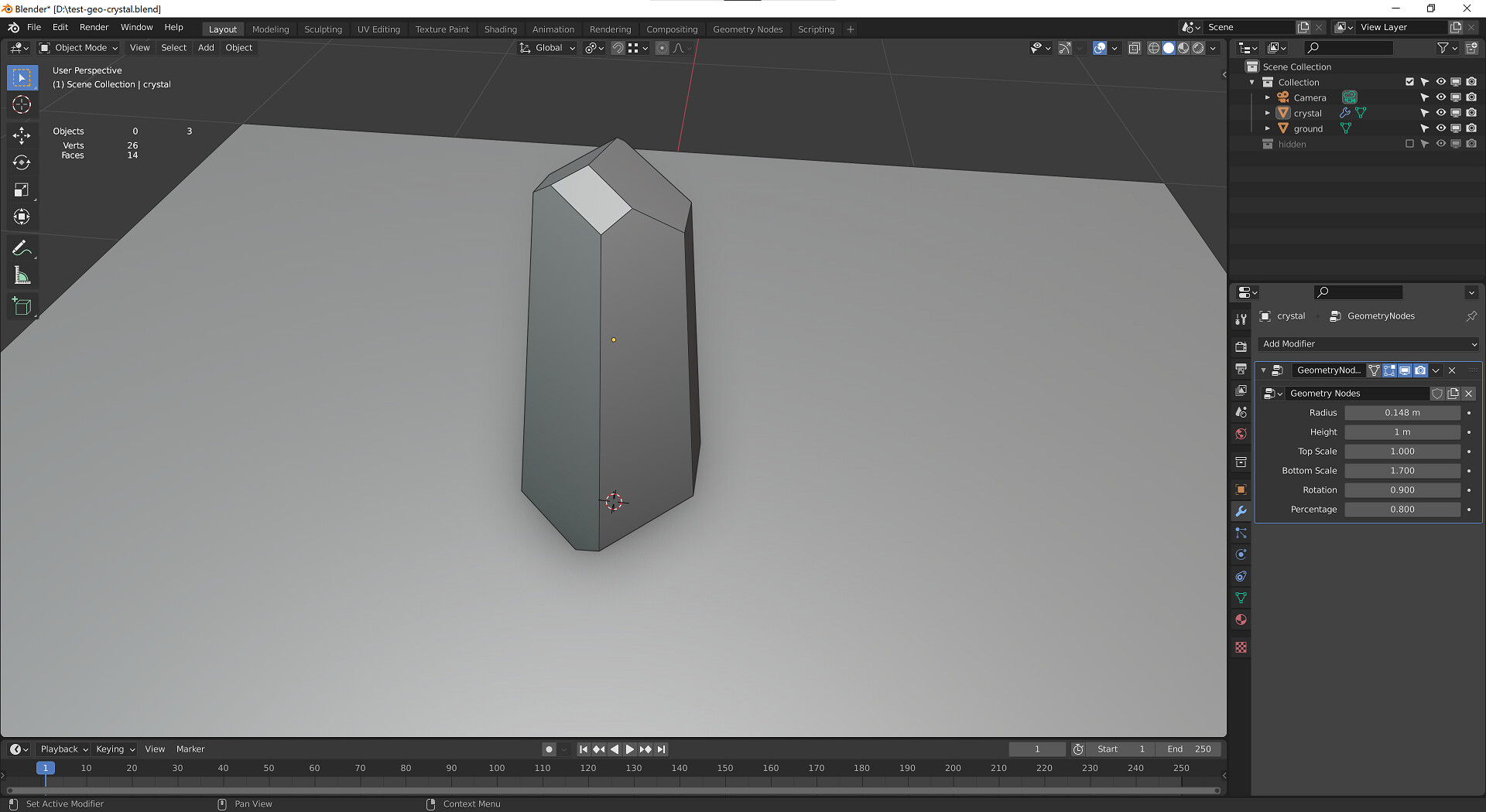
It’s not much, but it’s my first go at something not following any particular tutorial. Some procedural crystals, with lots of room for improvement later (like procedural inclusions and edge wear). I’ll probably take a few of these objects and use them inside another geo-nodes graph to get a procedural crystal bunch. Then I’ll take that bunch and scatter it around.
1 Like
I don’t know if this has been suggested or maybe is in the works, but the Switch node could use some readability, by renaming the inputs. It’s not immediatiely obvious which input is chosen when the condition is evaluated or not.
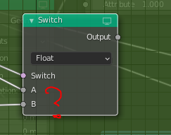
Maybe take notice of the AN Switch node which is (imho) clearer to the average user :
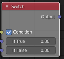
Also the inputs or inverted compared to the GN one so it’s a bit of a headache coming from AN ![]()
8 Likes
This is planned already as one of the community tasks: https://developer.blender.org/T88006
2 Likes
I’d still prefer Condition over Switch for the top socket, switches go on and off, conditions are true or false. Making a hybrid is… interesting… language wise…
2 Likes
Hello,
I had this idea for a while but could not implement it in Blender somewhat easily. With new geometry nodes I thought that finally it could be done. So what I want to do: I need to have an object which contains voxels in some way, colors of which could be accessed by Cycles volume shader.
The idea is to have some quite low-res 3D texture stored internally in blender object, which can be generated based on other geometry in the scene, etc. Think of it as of some modifier, so that during rendering this voxel data is fixed and has to be only read from the object and not calculated for each sample in shader. This kind of precomputation can significantly reduce render times if used correctly.
The simplest use-case is some distance field to several objects which you calculate only when objects are changed and in shader you just sample this distance field with some kind of interpolation.
This 3D voxel texture can be than combined with complex volume shader which through this texture can “interact” with objects etc.
As an example of how you could use it, you could generate a volumetric cloud using mix of noises in shader nodes and for color of this cloud you would use color of the closest voxel, color of which has been calculated as a mix of colors of nearby objects. In that case you can fake indirect lighting from these objects in a volume shader but without actually calculating any scattering. I hope that I made it clear 
What I’ve tried to implement this kind of behaviour:
-
Creating voxels as a bunch of cubes where for each cube all its verticies have the same vertex color. Then I can access this voxel data via Point Density Texture node. With correct values of resolution and radius it could be rendered truly as voxels.
Problems with this approach: Vertex colors have to be painted manually or generated through python script, so this method is not interactive, which is unacceptable for my needs. I guess that there is a bug with Point Density Texture node or Geometry nodes which does not allow to use them together. Any geometry generated via Geometry nodes is not displayed properly by Point Density Texture -
Another way is to use Points to Volume node. From the user point of view it generates a very similar results to Point Density Texture - for each vertex it creates a sphere with some radius filled with volume. This approach seemed advantageous to me at first, as it ties with Geometry Nodes nicely. The problem with this approach is that there seems to be no way to generate custom attributes which can be used in volume rendering; and also as this node generates Volume object there is no way to render it as a usual mesh, so volume is only rendered where density is non-zero. But I also want to control density via some 3d texture which can not be done in that case.
So I really hope that anyone can help me and come up with some idea to implement this.
Thanks in advance
1 Like