Would be useful if all duplicates were placed in a new collection after “make instances real” command.
Just having a really great time with the Line node!
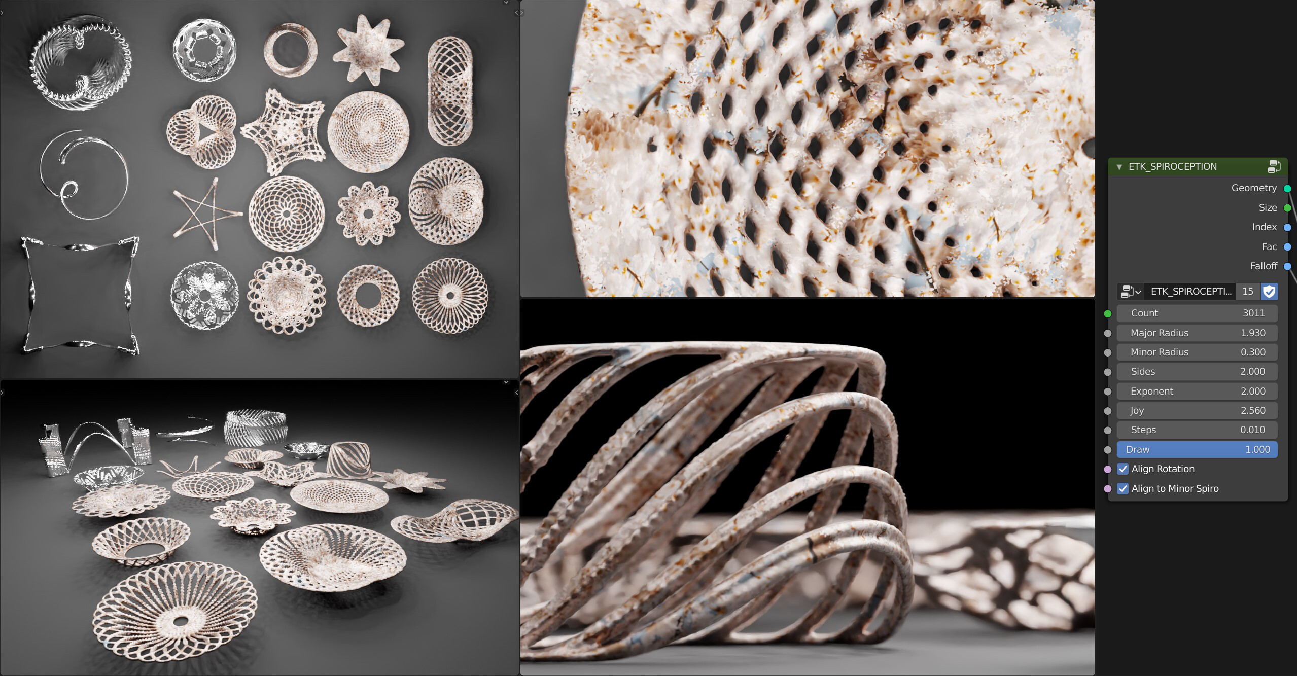
These are all made just setting settings on my Spiroception node (it’s just a Spirograph that spirographs a spirograph). A couple of other nodes like my stepped transform (that does an iterative transform based on index or fac) and a colourramp for the dish shapes.
28 Likes
This is really nice. Is this 100% geometry nodes or are you using any add-on?
1 Like
This is 100% geo nodes
Just the line node to create an index value and then a few layers of trig added together to get the spirograph effect. Bowl sides are pushed up using a falloff value that’s 0-1 gradient from the inner edge to the outer edge pushed through a colourramp. Instancing an icosphere and remeshing.
Fairly simple but super versatile!
18 Likes
Hi everybody, I’m an Houdini user but recently I get interested about the new geometry nodes in Blender.
I have a couple of questions about it:
- Is there a way to get the data of an attribute for a specific index in the geometry? Maybe it’s in development but it would be great if I could get specific attribute per index. Let’s say I’d like to grab the value of an attribute of the point 0 inside my geometry and then use it later on.
- How does nodes evaluate the geometry data? Do they loop through every points/polygons?
- How does edges are treated in Blender? In Houdini there’s the distinction between poly that are faces and polylines that are lines. Right now in blender the lines as far as I know are not considered as polygons infact inside the spreadsheet I don’t get any values in the polygons section.
- There will be some kind of loop system in the future?
Sorry for the long post. Be able to create some procedural geometry directly inside blender and get access to all the other features that blender is offering is really exiting.
By the way as a test I was trying to create a procedural vine and I encountered some of these limitations.
Thank you
2 Likes
Hi, as a long time grasshopper user, I’ve realised I am basically a newbie.

I tried to do something more complex, but I’ve realised I have to start pretty much from the beginning. So after watching a few youtube videos, looking through the examples here and asking @Erindale a few questions, I managed to do what I wanted to do.
First off, wondering if there is a more efficient way to achieve attractor influence?
Few thoughts and comments:
- The workflow at the moment feels quite linear, as the attributes seem to be linked to the geometry data. Shouldn’t the attributes live within the object itself so we can access them without the need to plug in the geometry? Perhaps an internal object dictionary. That would allow the manipulation of attributes without the need for a linear organisation. For example an attribute get mixed in with other things and then added to the main geometry chain.
- I know this may be tricky when trying to link in external geometry, however in that case the geometry should pick up the chain.
- Is it just me or do the X and Z vector coords seem to be flipped with apply rotation? I had to scale the x vec to get these to move in the Z direction?
- The spreadsheet is really good to see what’s going on, but it doesn’t pick up data not linked to geometry. E.g, if there is some vector math not linked to an attribute, it would be useful to have a way to visualise the result
4 Likes
So this is what set off my interest at the moment into GN:
I had to to inset the green faces and used a vertex group to mask out the vertices.
- Is there a way to slide the vertices along a normal direction?
- Could we access the face centre point somehow to use for vector direction for e.g. translating the points closer towards the centre?
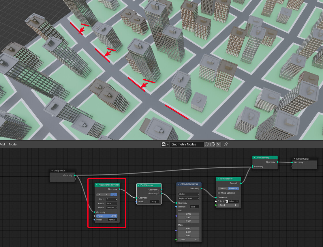
- I don’t think that the align position to vector now is done anything in this case. Am I doing something wrong? The node seems to pick up the normal attribute only before the separate node
- What would be the way to align the buildings along the normal directions of the edges?
On a separate note, what’s the plan for mesh editing tools?
What would be great is to start out with a base mesh, and be able to inset, extrude, set materials to get a city layout all within geometry nodes
Hi @dimitar, thanks for the feedback!
The fact that attributes are stored in the geometry itself rather than in the object or something else is really an essential part of the design, and it basically comes from the difference between objects and object data in Blender. The linear data-flow is definitely a common critique though, this design is meant to address that:
T85655: Attribute Processor for UX improvement
I’m not sure about these, maybe report a bug if you think it’s not working correctly?
I’m not sure that values from single nodes really fit in the spreadsheet, since there is only one value for the evaluation. But here’s another design task that’s related:
T85251: Nodes Preview: Socket Inspection
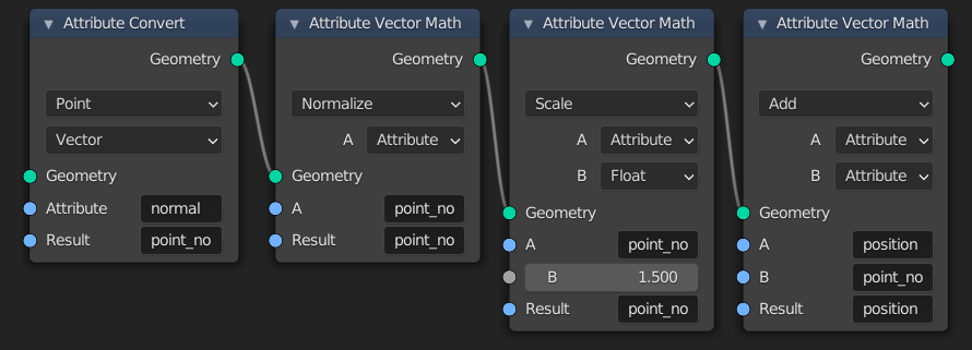
Yeah, something like this should work. The convert node moves the normal attribute from the face domain to the vertices, then it gets normalized, then move position by that value with some scale. It might make sense to put this in the manual actually, since it’s such a common operation.
I tested, and using the “Attribute Convert” node to convert position into a new center attribute on the face domain, then using that with an “Attribute Mix” node seems to work. An interesting problem!
For that I think we’ll need a “Tangent” attribute
That sort of work will likely start with converting existing modifiers to nodes, where it makes sense at least. Then I could see work on those sort of operations starting. The task for that is here:
T86839: Converting Modifiers to Nodes
5 Likes
There is no way to do this currently, though there may be other ways to accomplish what you’re trying to do here.
On a very high level, yes, that’s how the attribute nodes work at least.
Edges are treated as “Edges”! You’ll see that option in the drop-down in the spreadsheet header.
There are no plans for that yet, but I wouldn’t rule it out.
Thank you for your reply!
I edited a line inside the geometry node and I wanted to calculate a tangent vector for every points of the line. The intent was to subtract the current point position with the next-point position using the index of the points, but as far as I know I couldn’t do so without having access to the point data separately.
Maybe there is another way I was just trying and exploring the nodes.
Sorry I might have been a little unclear. I mean a line could be composed by multiple edges, so is the line a polygon? Inside the spreadsheet I can see all the edges but no polygons
Thank you!
Hi @HooglyBoogly. Thanks for the detailed responses!
A tangent node would be really handy to have for scattering all sorts of geometrical objects. Beside buildings, it would be useful for cars on the roads, lights, benches, etc.
1 Like
The normal vector just points straight up from the surface and doesn’t have any rotational qualities as far as I know. The axis will just be aligned to world axis which is why your buildings don’t rotate to follow mesh elements. What we really need is the ability to instance on edges for this to pick up the direction properly
1 Like
This is just awesome!
Fantastic! I like the last render with the texture and DOF!
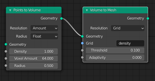
a quick tip: you mentioned, you have instanced an icosphere; you could go further away from external geometry and use these two nodes to get even more 100% geometry nodes to generate those bowls and plates!
1 Like
True true! That would save me remeshing as well!
Material is super easy it’s just a photo I found on Unsplash that I slapped on and made seamless with my basher node and then set roughness low and metallic high
2 Likes
Nice one! This moves towards the origin of the object. How about to the centre of face to which the vertices belong to?
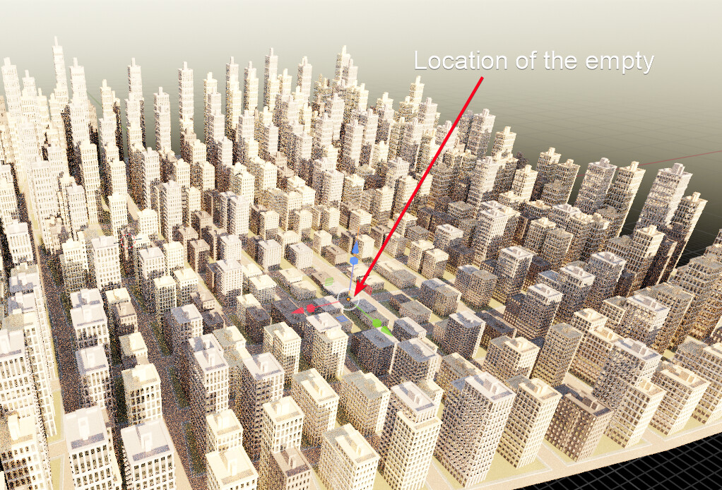
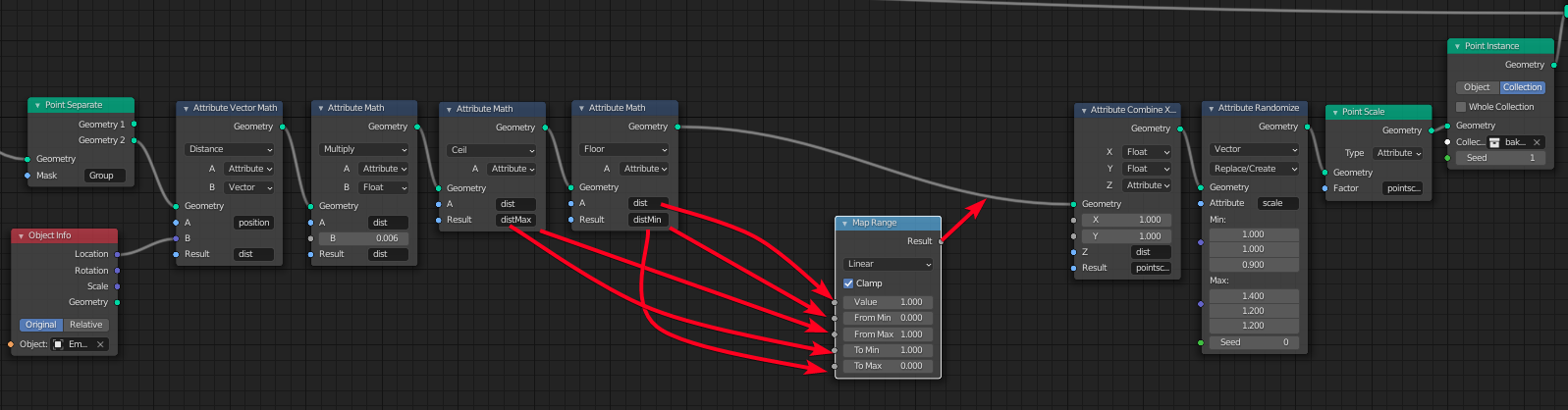
I am progressing with the city, with an empty acting like an attractor. Now, I wonder how I can remap the distance so the largest value becomes the smallest and vice versa?
So far, I am struggling with the attributes being always bound inside the geometry container without being able to be individually exposed outside. Excuse my ignorance if a way already exists?
If it doesn’t, could there be an Expose Attribute node so we can operate on those attributes independently and then add them back to the geometry container with Attribute Fill? That is, if lists can exist outside of attributes at the moment? Something along these lines:
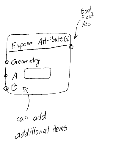
Another question - is it possible to write custom expressions with attributes? It could be an option in the Attribute Math node.
As a side note, the example above also shows the rigid linearity of attributes within the geometry container. There should be a way to get the max and min values without being plugged into the graph in the linear fashion as it currently stands. Here is an example of how attributes can be operated on independently of the geometry and then combined back when needed.
[ moderator: screenshot removed to keep this Blender-only. You should be able to explain this concept with original mockups or design on top of existing Blender features - reach out to @dfelinto if you need any clarification ]
Also note hote how the min and the max are exposed in one go, and two domains are constructed in parallel fashion. In Geometry nodes, the equivalent would be one long single chain, missing some of the potential of mixing, matching and parallel flows.
That’s a nice idea and it can “compact” some of the processing, but it’s still linear in the sense that the geometry gets input and then passed through the attribute processor and passed out.
Now, I wonder how I can remap the distance so the largest value becomes the smallest and vice versa?
I think there was a node in development called “attribute statistics” a while back that could gather and get min/max/average of an attribute. Not sure what happened to it. It hasn’t been brought up in a while. https://developer.blender.org/D10202
That’s a nice idea and it can “compact” some of the processing, but it’s still linear in the sense that the geometry gets input and then passed through the attribute processor and passed out.
Thats the idea. The geometry nodes isn’t designed to be like sverchok, it is meant to be a graph that defines a flow of modeling operations. The attribute nodes are a bit of a blight at the moment in complex graphs and long term should be discouraged in favor of manipulating attributes inside the processor. The attribute processor also has the benefit of being easy to reason about from the backend and be turned into optimized parallel operations. Hopefully this should explain things better.
1 Like
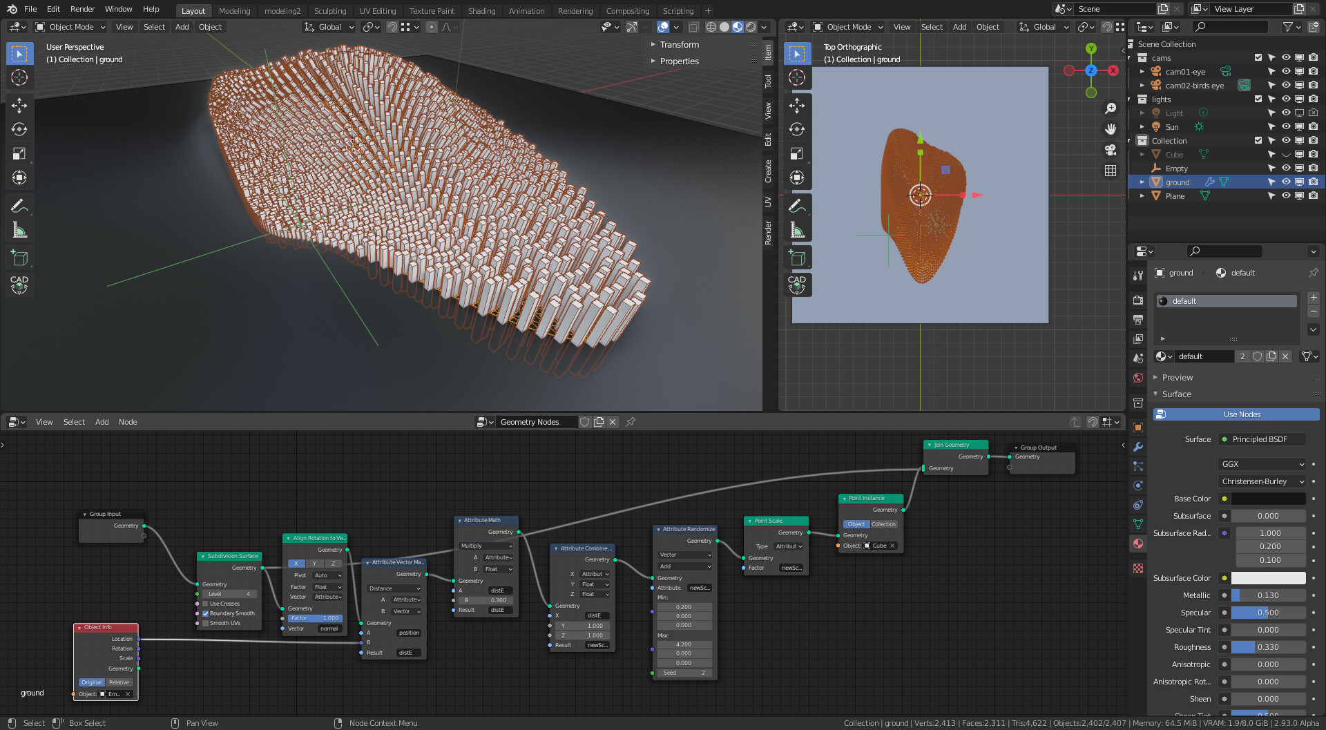
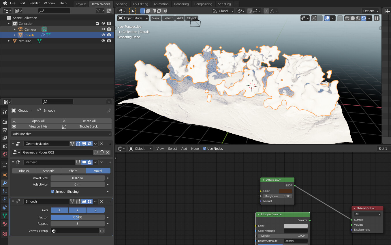
Hey all, is this a bug? When Geo Nodes is enabled the material renders as white instead of brown.
Edit: These are points converted to volume converted to mesh. It appears that if I join the original plain with the new geometry I do get the material working… soo is this a bug or a feature?
1 Like
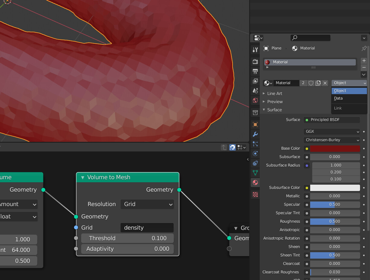
It is a feature but being ironed out I think. You need to assign the material to your Object instead of Mesh data as generated mesh doesn’t have the material assigned to it. It’s a hierarchy thing. You can change it here:
2 Likes
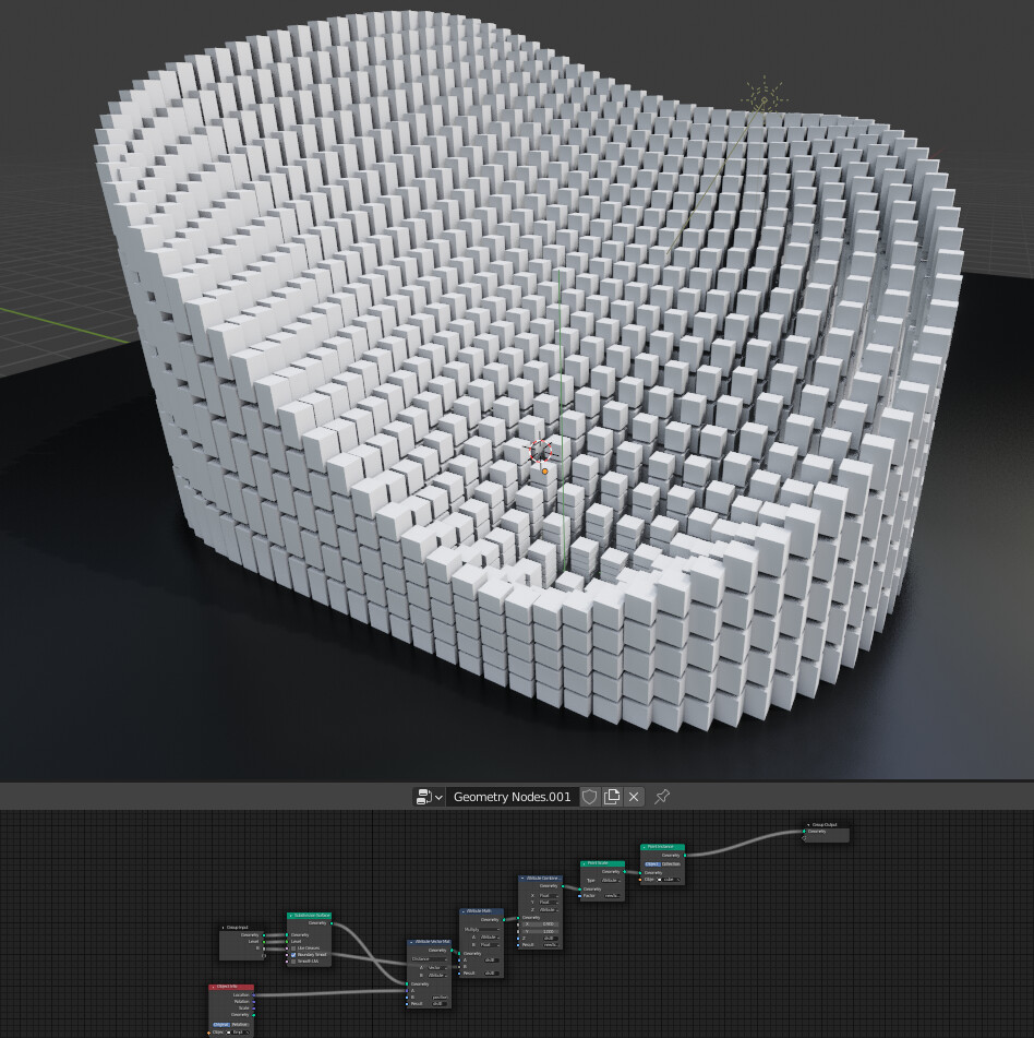
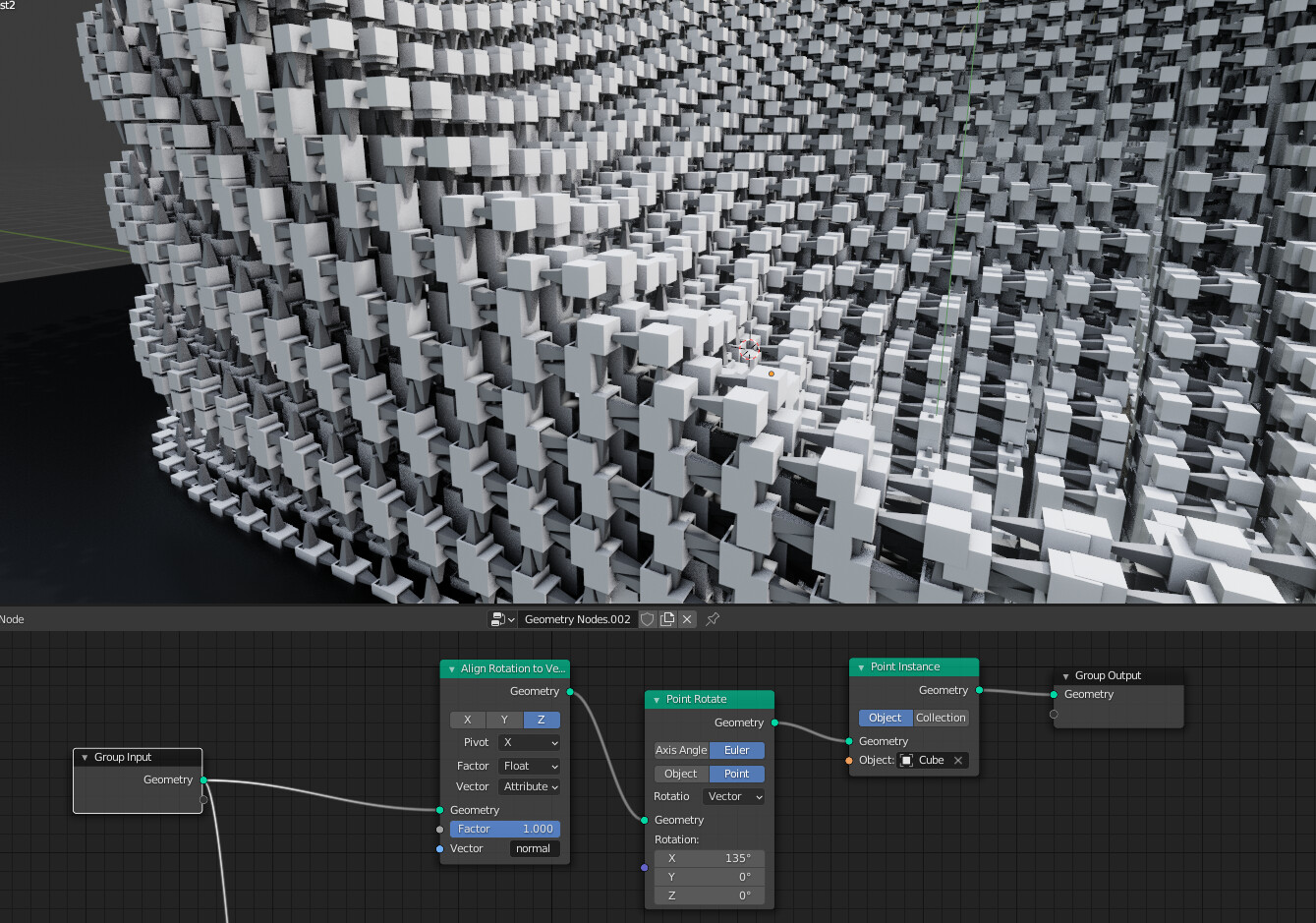
More experiments. It seems to me that Point Instance should be able to inherit the normal orientation in the same way that Point Distribute does. Perhaps there could be an option to inherit rotation.
However, what we really need is a Face Instance node, since there will always be issues with the normal directions of vertices
This example uses two GN modifiers. The first one instances the cubes and the second one instances the pointy cubes along the already instanced cubes. I am struggling to control the orientation
And a few videos on twitter of the same process
2 Likes