+1
I understand the desire to avoid any ambiguity by restricting Geometry to one Output.
But UX is annoying when all Attributes Outputs have to be collected by the same node because 2 Group Output nodes are not supported.
I think that node automatic insertion is also degrading UX a lot.
The connection automatically done is non-sense when node inserted has no Geometry Output (Attribute Statistic, Attribute Transfer, Color nodes, etc…).
Connections are now coloured. That does not mean that automatic insertion does the difference between connections where the node can be inserted meaningfully and those where that does not make sense.
That is also time consuming to have to remake connection when you just want to work on an original instanced geometry because muting Instance on Points node is showing points not the original geometry. It would be welcomed to have Shift F when Instances on Points is selected to switch connection of muted node. I wish there was a way to disable it.
Shift Ctrl Left click on a node will connect it to Geometry Input of Viewer node and as a result, nothing changes in Viewport because connection of Group Output node is still the same.
Under other context, viewer is showing expected result (a shadeless material or a composited image) , not the spreadsheet version of it.
Same kind of simple direct connection to Group Output is needed for Geometry Nodes.
Although Spreadsheet is useful, main editor where result of GN trees is inspected is still the viewport.
Hi everyone. Does anyone know if the below action is possible with geonodes? the idea just came up as a potential solution to a problem I have been struggling with for weeks. here’s a description of what I want to do:
So with the Capture Attribute node I can store attributes and use them much later even after converting the geometry to other types (say curve to points)
I will like to offset this captured attribute along its index. For example, Imagine I have a curve with 3 points right. then I capture the Curve Parameter such that point 1 has a parameter of 0, point 2 has a parameter of 0.7 and point 3 has a parameter of 1.0. Now I will like to move the captured curve parameter on each point to the next/previous point index such that point 1 now has a parameter of 0.7, point 2 parameter is 1.0 and point 3 parameter becomes 0.0 (at the end where there’s no attribute to offset it becomes cyclic and picks the first point index)
Is this possible? Does my description make sense? If not let me know and I’ll make a proper descriptive image or video showing what I’m trying to achieve.
Thanks
P.S. I already posted this in the blender artists thread but feel like I might get different opinions here. Apologies if you’re seeing this both here and there
Hi, you should be able to use the index input node when transferring attribute (by index) and subtract a number from it.
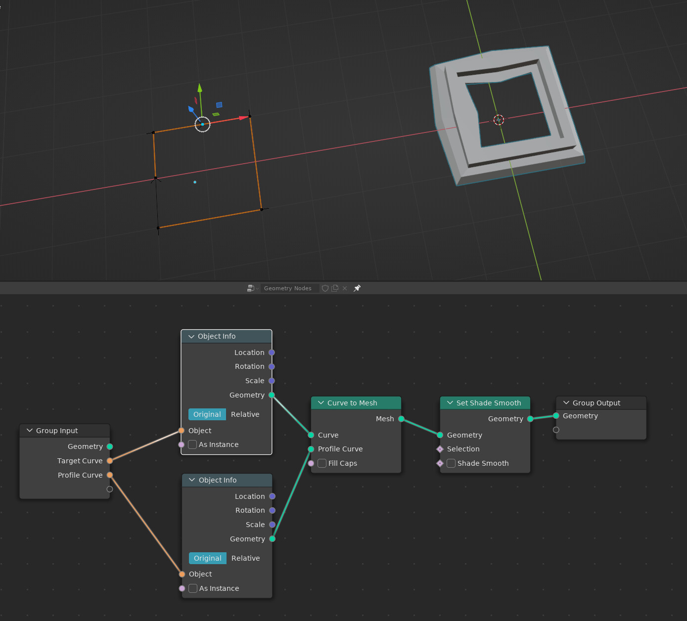
I’m perplexed : I’ve been trying to import output attributes from another object to use as fields, but I cannot find a way ? shouldn’t there be outputs from the object info node or something ?
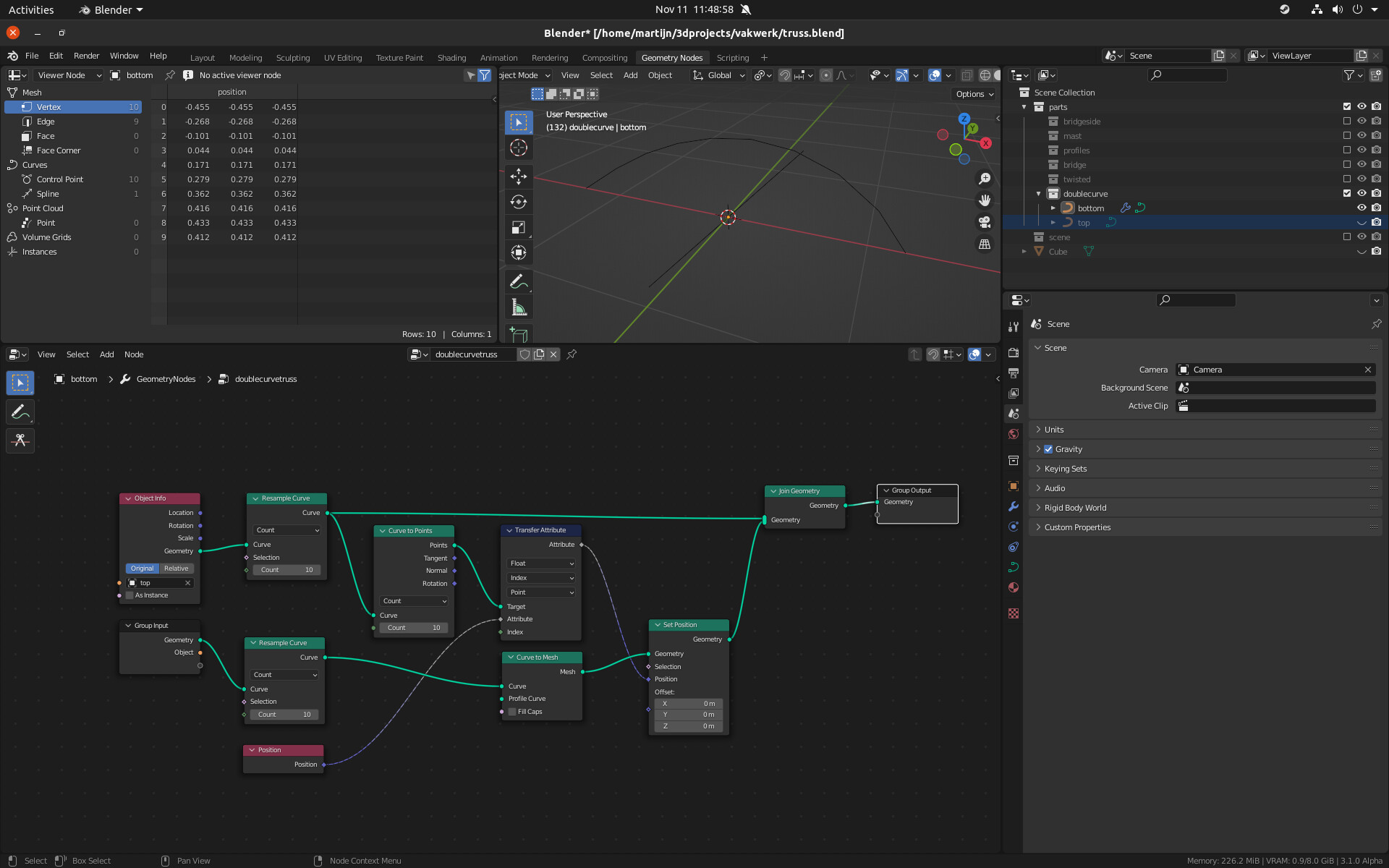
I’d expect the effetc of this tree to be that the positions of the top curve’s 10 points are transferred to the bottom curve’s 10 points.
But as you can see the positions (shown in the spreadsheet) are completely wrong. Is this a bug? Do I still misunderstand how it’s supposed to work?
edit: woops, I meant to reply to @Hadriscus . @Astronet please excuse the noise.
edit2: Nevermind! I found it. Looking at my post I suddenly saw that I had chosen the float output instead of vector.
I still don’t really understand how the positions vectors get converted to such small floats, but at least with vector output it works.
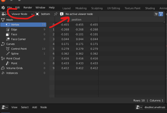
Not 100% sure, but you probably see something else than you expect in spreadsheet. You have “Viewer node” set as preview, but right next to it there’s warning message “No active viewer node”!! Changing it to Evaluated may fix your problem.
hahaha the tiny legs ! awesome. I expect future rigging nodes will allow for procedural animation like this, but in a more friendly way. Cool experiment nonetheless
There is already a better way of doing it: f-curves. There you can nicely see at a glance whether the sine tops align or not. Rule of thumb: the prettier the wave pattern, the prettier the movement.
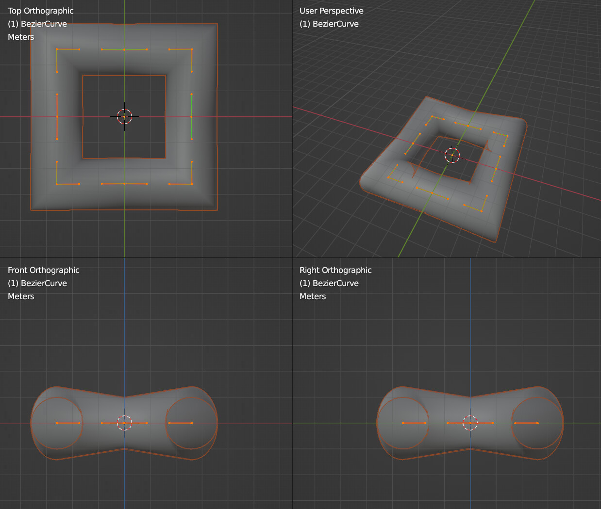
the curve bevel in object mode in Blender always sucked a lot because it was unable to properly create even offset profiles, unless one set the Shape type in curve to 2D instead of 3D, which was a dealbreaker. Ability to sweep any custom profile curve along any other custom curve is essential tool for most of architectural modeling, and one of the reasons archviz people often got frustrated with Blender.
I was hoping that GN would finally remedy this, and that the Mesh to Curve node would finally do this right. But to my surprise, the result seems to suck as much as the Object mode in the Shape panel of curve objects:
Does that even work in other software ? I don’t expect the curve to mesh node to know whether it’s dealing with a corner or a straight line. Right now it just gives the same thickness to every point… I guess you would like it to apply a scale of √2 on the corner points ?
If you delete your middle point (the one that’s selected here), it should work fine.
That’s the point. I don’t want to delete those There are many cases where you can’t afford to do that. It’s a very simplified case, but the point is that it doesn’t happen only in this case, it happens on many more rectilinear shapes, sometimes even if they don’t have points on straight lines. And yes, there are other 3D packages that handle it properly. I mean even Blender handles it properly using the Bevel set to Custom Object in the Shape panel of a curve object, but only if the curve is in 2D mode. I was hoping that with GN, I would not have to do this compromise anymore.
I think it’s actually doable, it needs to adjust the radius scale on the axis of the bend, depending on how big the angle is. It should be an option though, because at very small angles, that scale tends towards infinity. It’s probably not so complicate to implement, but also not trivial.


 There are many cases where you can’t afford to do that. It’s a very simplified case, but the point is that it doesn’t happen only in this case, it happens on many more rectilinear shapes, sometimes even if they don’t have points on straight lines. And yes, there are other 3D packages that handle it properly. I mean even Blender handles it properly using the Bevel set to Custom Object in the Shape panel of a curve object, but only if the curve is in 2D mode. I was hoping that with GN, I would not have to do this compromise anymore.