Thanks a lot! It really worked.
It is not clear only with what limitations is connected with the fact that this function is in experimental?
Hello @dfelinto
Could you explain how plans made by the team such as the checkpoints node:
Geometry Checkpoints
Sometimes artists need to use procedural tools, manually tweak the work, and then have more procedural passes. For example, an initial point distribution can be created using Geometry Nodes, then frozen. At that point, the artist could go to edit mode, delete some points, move others around, and then use Geometry Nodes again to instance objects.
from: https://code.blender.org/2021/07/nodes-workshop-june-2021/
Are compatible with the strict share-ability paradigm?
Because it seems that the object/collection info nodes are not just the few exceptions to the rule:
In the long term, more ‘exceptions’ nodes could pop such as:
-scripting nodes ( listed in the recap)
-any nodes that read/write data: cache/ file import&export / objects/ materials/ collections/ images/ audio-data ect.
-any kind of nodes that would require an user-interaction with an operator.
And in short term:
-i suppose the ‘delete attribute’ node will need to do a comeback.
-the new Image-data/material nodes will need to be added to the ‘exception’ list.
If the rule has too many exceptions, perhaps the exception is the rule itself ![]()
It’s done now!
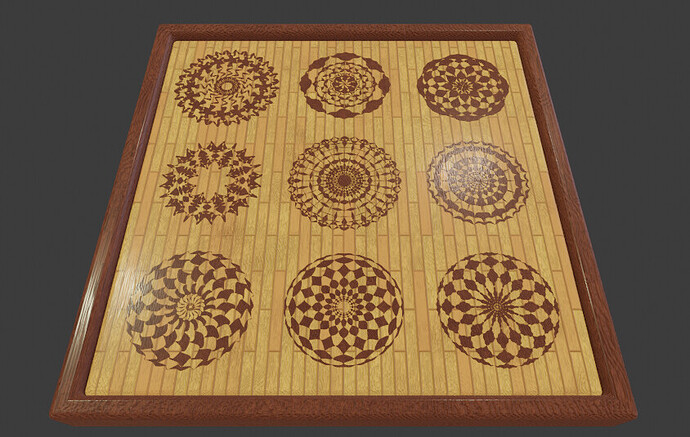
@dfelinto This is a submission for GN Fields demo file, not sure if my skill is good enough but I hope this file is okay
How beautiful! Thanks for the file!
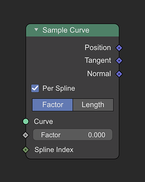
I made this animated geo nodes file, it might make a cool demofile but due to an issue with the Evaluate Curve node, it’s probably not a great example at present:
The issue is that with multiple splines, even in Parametric mode, the spline length is used to calculate the parameter ratios, so trying to instance across multiple curves in one nodetree is basically impossible, as far as i can tell. The solution was to recreate the curve eval by hand.
I can update it if/when the curve eval node could be used for it ![]()
@dfelinto Can I have some feedback about whether my file satisfies the condition for demo files, or is there something I need to improve or fix? I have been kind of nervous about this, hehe.
(this is a video demonstrating the problem with the sample curve node i mentioned above)
IMO if it’s being used in Factor mode, each spline segment should be equal. If you wanted to weight the splines by length, then you’d use Length mode, it doesn’t make any sense at all to use the spline lengths here.
I think both are needed. It’s reasonable to treat a curve with multiple splines as one, it depends on the use-case.
This isn’t the first time this problem came up.
For handling both use cases I had suggested to have an option for it, so we could treat it as one combined curve or as individual splines:
Hi, first of all, nice file 
Second, this file helped me already to find a potential bug.
This is one of the reasons it helps so much to have those demo files. There is only so many bugs we can find by playing with cubes and monkeys [the bug coincidentally got fixed 10 minutes before I sent its bug report].
I just added your file to the Geometry Nodes project page. We may need to trim the list down and do some curating when sharing them in the blender.org download page. But the file will help testing and other artists regardless.
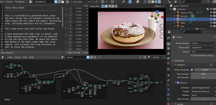
I have just added the new sample files in the top post:
- Pasta Planet by Eric Schubert

- Chocolate Donut by Zijun Eary Zhou 法纤净

You know what would be really useful for asset pack creators?
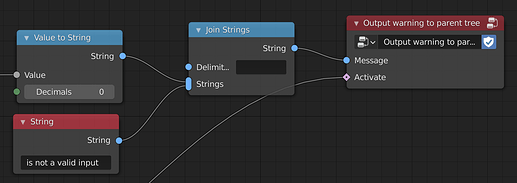
I propose a node to output warning messages to a nodegroup or modifier. It would let users output these:

I think this is essential for share-ability and any nodegroup creator creating an asset pack for beginners.
Of coarse, so beginners don’t spam the tree with irrelevant messages, it could be activated by an advanced option in user prefs.
Thank you, added to the sample files 
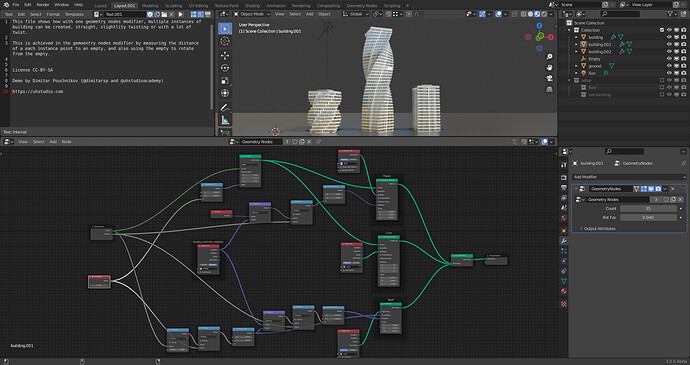
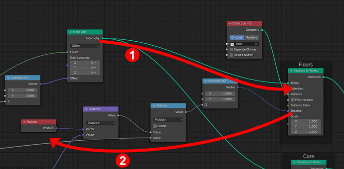
This is the first time I’ve tried to port one of my files from Attributes to Fields. It is a typical building setup, where one floor has been modelled, distributed and twisted. I have been using an empty as a hack for distances from points. In other software, I would construct a domain with the upper and lower Z bounds, and multiply each successive item in the list by a rotation factor, but I don’t know how to do this in geometry nodes yet. The setup as is with the empty feels pretty straightforward. The only abstract bit for me is how the position node knows what I need the position of.
Here is the file: https://pasteall.org/media/6/0/6009b02963c89b54caa0a4aef221b523.blend
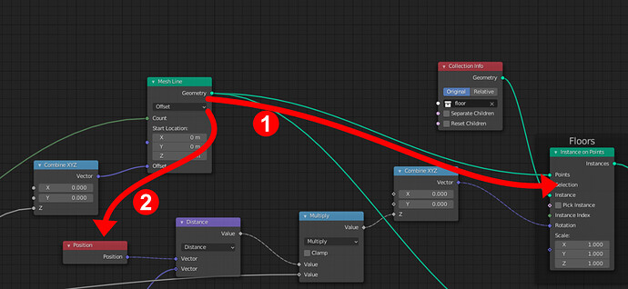
That’s the new “field” stuff. Basically the Position node doesn’t carry any data. Think of it as a placeholder for an attribute name. It’s only once you plug it into a node that acts on geometry that the field is evaluated.
I see, I guess reading this feels a little odd at the moment as a complete Fields newbie, where first the input comes, then the rotation in this case knows that is is picking up the points defined elsewhere because they meet at the points instance.
It’s definitely a big improvement over the linearity of the attribute specific nodes, where everything had to be daisy chained. Coming from that experience, I suppose I understand that an attribute has to be tied to a specific geometry. It just somehow feels that if there was some sort of way to pull the Position directly from the points, it would be more comprehensible.
But in any case, I am sure with more experience it hopefully becomes easier to understand where how nodes like Position might be picking up their field from where. It just introduces now the understanding of reading the graph both left-to-right and right-to-left
There is ! this is what the attribute capture node does. However in your case, it is not needed, since what the position node is giving you is the position at the relevant point. If there was another node in-between mesh line and instance on points modifying point positions (such as translate), then you’d need to capture the points position as they are before the translate node, and that’s where capture attribute comes in. It’s also pretty intuitive because it inserts itself in the geometry flow, effectively “extracting” the attribute at that point (still believe it should be called extract attribute but hey).
i know this question is out of the subject but, how did you manage to assign the colors of the sockets to the colors of the wires?
It’s the default settings in the latest alpha. Might need to delete your current 3.0 prefs
Thank you it’s a cool features !
