Discussions for "Better snapping and precision modeling"

My background:

Retired, but still only 62 years old.

Qualified Engineering Drawing Teacher, Mechanical Engineer, Mechanical Designer, IT Developer. Started in drawing office 1978, started with CAD 1981.

CAD Packages used: Intergraph IGDS, Bentley MicroSystems, Matra DataVision (Euclid), SolidWorks, IBM Catia, FreeCAD. AutoCAD in 1987, briefly - hated it!

As a design engineer I can see many things I would like in Blender to make drawing mechanical parts better (CAD Functions), along with the suggestions already made here, might I also add:

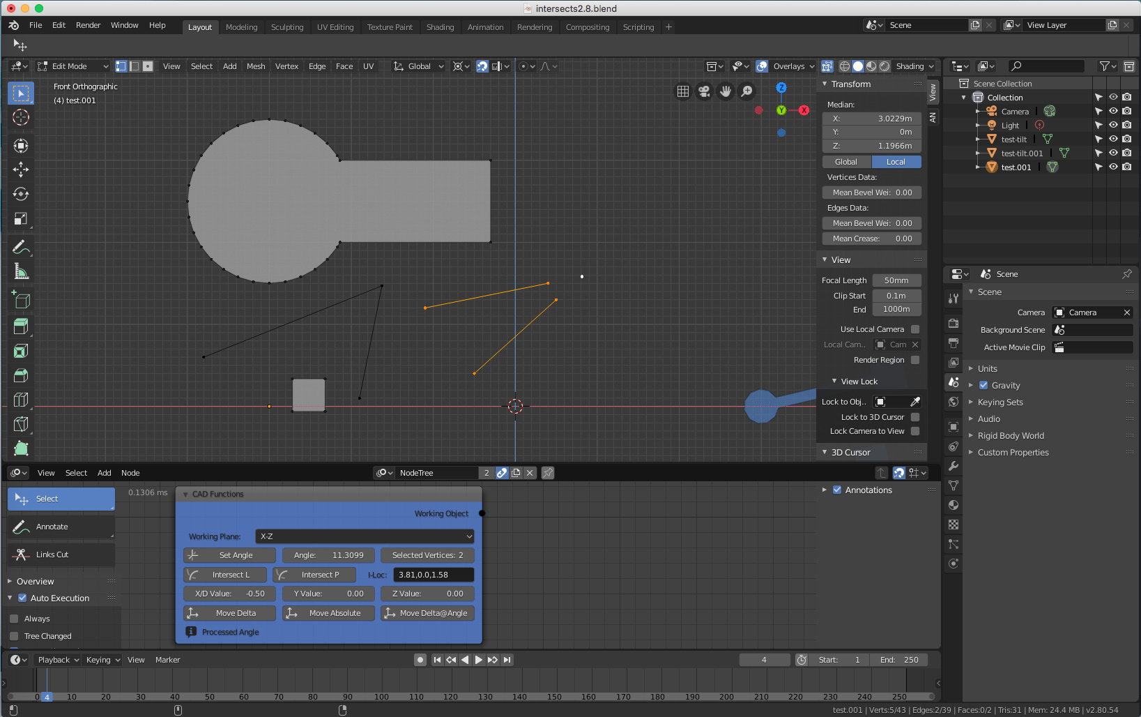
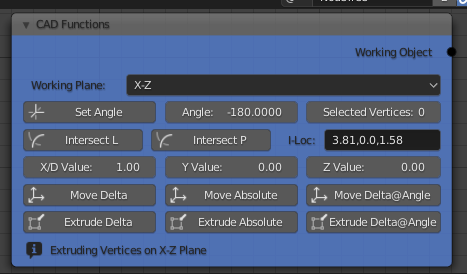
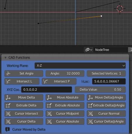
  1. Ability to extrude a vertex, or series of vertices, by a delta coordinate from its position, or by a delta length and rotational angle relative to the view plane.

So a workflow like: select vertex, extrude, key DC 1.2,1.4,0 extrudes the vertex 1.2 in X, 1.4 in Y and 0 in Z. Or key DR 1.3,45 extrudes the vertex 1.3 at an angle of 45 degrees relative to view positive X (3 O’clock).

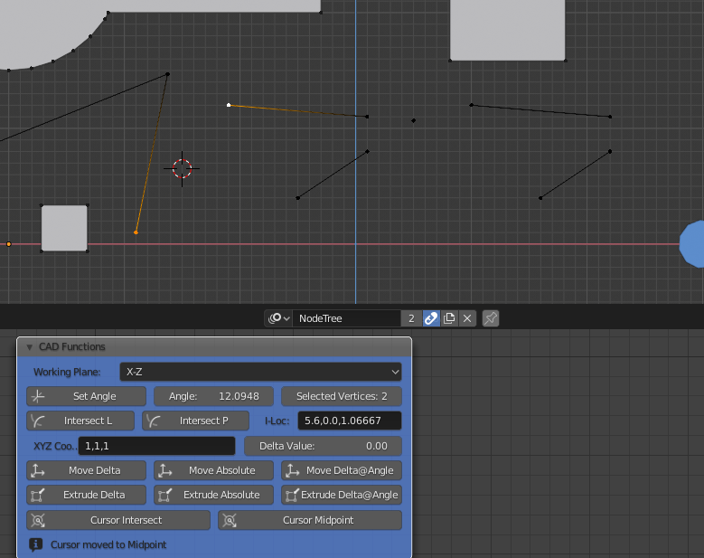
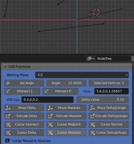
  1. Ability to use a “Tentative Snap” (T-snap) to an existing vertex.

So a workflow like: select a vertex, T-snap any existing vertex, accept this location, or key a delta offset like DC 1.2,1.4,0 or DR 1.3,45. This gives us the ability to use another vertex on the model as a starting point for a delta offset.

  1. Ability to use an absolute 3 axis location.

So a workflow like: select a vertex, extrude, key XY = 1.4,2.6,3.0 this extrudes the vertex to the absolute coordinate given.

  1. Ability to input an absolute, or T-snap + delta input to place a new single vertex.

So a workflow like: add vertex, key XY 1.4,2.6,3.0 or T-Snap existing vertex and key DC 1.2,1.4,0, or key DR 1.3,45.

  1. Ability to add primitive shapes at absolute, or T-snap + delta input.

So a workflow like: add rectangle, key XY 0,0,0, key DC 2,1.3 creates a rectangle with the bottom left vertex at 0,0,0 and the top right vertex at 2.1,1.3,0.

It is assumed that 0 input need not be added, so DC ,3 means delta 3 in Y axis, for example. XY 0 means all inputs 0, etc.

  1. Close a polygon after so many vertices have been added.

So a workflow like; add vertex, extrude, key DC 1.2,0,0 key DC 0,1.4, etc, etc, some command to close the polygon, i.e. join the last vertex to the first one.

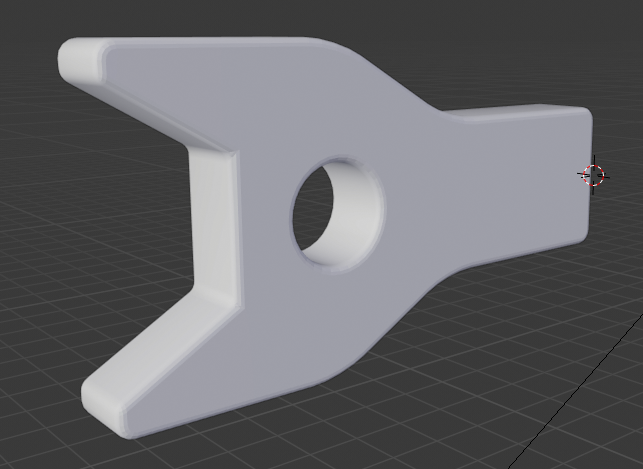
The ability to create a single vertex and then extrude it around a coordinate defined path then close it is a fundamental requirement for CAD. The ability to tentatively snap a vertex and use this to place a new vertex, or extrude an existing one will greatly improve the workflow and reduce the time taken to create geometry.

  1. The ability to create “parts” of geometry in a library. I know you can do this by creating objects in a blend file and then appending them, but the workflow is not CAD friendly.

So a workflow like; create a geometry - a bracket for example, that will be used extensively in the model, or in many models. Add this to a “Parts” library so it can be easily recalled later (think Pose Libraries…). Each part has an origin and is placed with the origin at the cursor location, or using a T-snap and delta input.

  1. Ability to extrude a vertex along the path defined by itself and the previous vertex, or to extend the vertex along the same path without adding a new one. So if you have an edge from 0,0 to 3.4,5.3, extrude this to make a straight line of three vertices, or move the end vertex in line with the path defined by the two vertices by a set distance, i.e. make the line a bit longer without changing the angle of the line.

Imaging here you have made a hydraulic cylinder at an angle of 23.45345 degrees to the horizontal and you want to make it 2cm longer, without that operation taking you half a day…

  1. Ability to rotate the view by a set amount, like say 46 degrees about its normal axis for example, or 37 degrees about the global X axis.

As a design engineer working on a drawing board, I would start with construction lines and work from there, I don’t see the need for this in Blender, if T-snap & delta inputs can be achieved. Things must line up in technical drawing, so T-snap is a must. In all the products I have worked with, Intergraph IGDS was the easiest to use to rapidly create precise geometry. It had a “T” button on the cursor and the ability to input 3 axis absolutes and delta offsets. It also had a Parts Library, although it was called a “Cells Library”.

I don’t see these additions as a large amount of work by the way, just some additional key-ins and the T-snap to make life such easier. The other function I used extensively in those days was “Copy Parallel” - this we have with the “Offset Edges” add-on, so this should be included as well. I also like the ability to select two vertices and join them with an edge, I am not sure if Blender can do this easily, I know we can select two unconnected edge strings and make a face of them, but this is not quite the same thing…

While I am on a flow here, could we also add the ability to create shapes within shapes as holes without having to add a least two edges from inside loop to outside loop, thus creating two Ngons that don’t have holes…

I think that basic, efficient draughting techniques have been lost in not only 3D modelling packages like Blender, but also many CAD packages, the old ways were not always the best, but they certainly had a lot of merit. Systems in the 1980’s had to be very efficient and fast to compete with a good draughtsman and had to run on computer systems that were toys (think VAX PDP 11’s) compared with today’s machines.

Let me know if anyone agrees with me, I am more than willing to expand these ideas, if they are thought relevant still, otherwise I can always enjoy my retirement!

Cheers, Clock.

12 Likes

Oh, I forgot this one:

I would call this “Extend/Trim to Intersection” - select the two edges in the set and the system puts the intersecting vertex in place then trims/extends the edges to this point. I have shown three possible scenarios of this requirement.

Cheers, Clock.

7 Likes

OK just a quick test to see how easy this intersection lark is going to be:

I am on holiday with only my wife’s MacAir, so only have access to Blender 2.79. I made an object with several edges, to test it worked on selected edges only. You can see the new vertex at the intersection point. This is the code in a simple Animation Nodes Script node:

import bpy
import bmesh
import numpy as np
mesh = obj.data
verts = mesh.vertices
edges = [e for e in obj.data.edges if e.select]
lv1 = edges[0].vertices
lv2 = edges[1].vertices
# Working in X-Z plane
a1 = (round(verts[lv1[0]].co[0],4),round(verts[lv1[0]].co[2],4))
# Get Y value
yV = round(verts[lv1[0]].co[1],4)
a2 = (round(verts[lv1[1]].co[0],4),round(verts[lv1[1]].co[2],4))
b1 = (round(verts[lv2[0]].co[0],4),round(verts[lv2[0]].co[2],4))
b2 = (round(verts[lv2[1]].co[0],4),round(verts[lv2[1]].co[2],4))
# Get Intersection
s = np.vstack([a1,a2,b1,b2])
h = np.hstack((s, np.ones((4, 1))))
l1 = np.cross(h[0], h[1])
l2 = np.cross(h[2], h[3])
x, y, z = np.cross(l1, l2)
if z == 0:
    # Parallel Lines
    int = (float('inf'), float('inf'))
    return
int =  (x/z, yV, y/z)
# Create Intersection Vertex
bm = bmesh.new()
bm.from_mesh(mesh)
bpy.ops.object.mode_set(mode='OBJECT')
bm.verts.new(int)
bm.to_mesh(mesh)
bm.free()
bpy.ops.object.mode_set(mode='EDIT')

There is no “Stupid User” testing in there, like making sure the edges are co-planar, but I can always do this later when I get home, or leave it to the experts… I guess next I will need to move the nearest vertices to the intersection, or simply delete them and re-define the edges. Further development on holiday will be curtailed now as it is “Gin & Tonic” O’Clock. :cocktail:

Cheers, Clock. :stuck_out_tongue_winking_eye:

EDIT:

It seems I cannot post any more replies until someone replies to me (new user), so here is another function:

Merde! I can only post one image in a reply here, so you will have to wait to see the picture… Thousands of posts on Blender Artists, but not trusted here yet…

In this one I have moved the square end a set distance along the angle of the centre section, i.e. expanded the object along its centre section axis, which lies at approx 13.24052 degrees to the horizontal. Try doing that with native Blender in 2.5 milliseconds!

When I get home I will make a “CAD Functions” node to do these functions, using Exec buttons. The maths behind them so far is pretty easy, if you know your numpy, geometry, etc principles. Perhaps, if you would like to reply here with other functions required, I can make a CAD Node and release this on my GitHub.

As you will see from this link, my work has been with MIDI, Sound, DAW functions mainly and some other useful bits for Animation Nodes. I see no reason why this cannot just be a AN CAD sub-section to start with, then maybe it can be included in Blender, or Everything Nodes, at some later stage, if there is sufficient interest.

I am still keen to explore the possibility of adding extra key-ins to vertex placement/extrusion, like an Absolute XYZ, or Delta-Coordinate, or Delta Distance-Angle.

I shall await responses!

4 Likes

I haven’t dug deep enough into the codebase to layout a concrete plan, but I think that, if we can separate transform orientations and alignment orientations under the hood, we can expand the existing snap system to cover a lot of “snap-to/align-to projected intersection” scenarios we’ve seen in this thread.

Some of the other things you mention, like transforming from an offset position and extruding at a relative angle, could (theoretically) be implemented with gizmos and the active tool system. You can abuse them as pseudo-modals to take data from selections and create transformation matrices at relative angles.

5 Likes

@ThatAsherGuy Yes, I agree, we can already key such things as X, XX, R, S, etc. so I don’t see a great deal of work in adding some more options to the module that allows the existing key-ins for duplicating objects, extruding vertices, etc. Like you, I have not looked “under the hood” to see how these are implemented. It would also be good to get ideas from more users who have used draughting techniques in their occupations.

At the moment, if you want to duplicate an object, or extrude a vertex (including multiples thereof) in multiple axes (1 in X, 2 in Y, 3 in Z), the process is like this:

  1. Select Object(s)
  2. Key SHIFT+D
  3. Key X 1
  4. Key G Y 2
  5. Key G Z 3

Or, you could place the cursor at the required location for a single object then key SHIFT+S => “Selection to Cursor”, but this only works for one object. You could also type in the transform boxes - say click in the X Transform box, Right Arrow to end of existing entry, key +1 and Return. Repeat this for Y and Z boxes for each object if many are to be processed, this is all time consuming. Example below:

27

With what I am proposing the process is this:

  1. Select Object(s)
  2. Key SHIFT+D
  3. Key DC 1,2,3

For duplicating along a slanted vector (3m at 30 degrees anti-clockwise in front view), the process is this, only works on one object BTW:

  1. Select Object
  2. Key SHIFT+D
  3. Key X 3
  4. Place Cursor at original object origin
  5. Set 3D Cursor Mode
  6. Key R -30
  7. Set Cursor to new object origin
  8. Key R 30
  9. Apply rotation to duplicated object

With what I am proposing the process is this, works on many objects as well:

  1. Select Object(s)
  2. Key SHIFT+D
  3. Key DR 3,-30

I would use basic Trigonometry to alter the coordinates of the duplicated object, so for the X delta use [existing X]+(3*cos(30*pi/180)) and for the Z vector use [existing Z]+(3*sin(30*pi/180)). Note I am converting the angle in Degrees to Radians, the maths is not complex for these DC and DR functions. I would also add an XY function to move an object, or vertex to a known absolute, e.g.:

  1. Select Object
  2. Key SHIFT+D
  3. Key XY 1,2,3

For manipulating vertices, either to duplicate, or move, or extrude them, I would propose using the same principles, hoping that the same module for transforms is used…

I am quite happy to work with the devs in specifying such a modification to the “Transforms” module. Is there much support for these CAD functions, bearing in mind the advances in 3D printing from Blender and the pricing structure for many CAD packages? I just want to make the draughting processes much easier and more capable.

PS. Here is my image from my previous post, now that I am a trusted user:

26

This shows the original object at the bottom and the modified one at the top. This is the code in the script to do this:

import bpy
from math import sin, cos, pi
verts = [v for v in obj.data.vertices if v.select]
if len(verts) > 0:
    for v in verts:
        v.co[0] = v.co[0]+(offset * cos(ang*pi/180))
        v.co[2] = v.co[2]+(offset * sin(ang*pi/180))

The code only works in X & Z axes, but would be easy to adapt to any axis combination and would need mods to work in 2.8, but you should see the principles.

3 Likes

One more thought on this:

I just did a quick Internet search for AutoCAD pricing in the UK - £1500 + VAT per annum, or £4050 + VAT for 3 years, Bentley MicroStation - £250 per month per user. Hmmmmm how about making Blender more attractive to CAD background users…

In 2.8 you can rotate the 3D cursor, which cuts this process down significantly. When you combine that feature with using the 3D cursor as a pivot point (which lets you control the offset distance when snapping), you can speed up a variety of workflows.

4 Likes

So, after about 4 hours work and some previous research I made this AN node:

What does it do? Answers below:

  1. Set the mode to which plane you want to work in; X-Y, X-Z & Y-Z.
  2. Calculates the precise angle subtended by two vertices.
  3. Extends/Trims two non-parallel edges to their intersection point.
  4. Draws a vertex at the intersection point of two non-parallel edges, without altering the edges.
  5. Moves the selected Faces/Edges/Vertices by a given delta offset in three axes simultaneously.
  6. Moves the selected Faces/Edges/Vertices to a known absolute XYZ coordinate, removing all doubles.
  7. Moves selected Faces/Edges/Vertices by a given delta distance at a given angle.

You can use the Angle function to set the given angle for a move by selecting two vertices, centre first, then offset - these need not be an edge. You can move all selected geometry by a delta amount in all three axes as one operation, good for altering a mesh at an awkward angle. You can move selected vertices to one given XYZ location, this makes them all coincident, then removes the doubles.

You can either trim two edges to their intersection, or place a new vertex at that location, this is good for finding convergence points to make new geometry, or to intersect a line to a circle for example. All action require you to simply select some geometry and then just click the appropriate button.

I will think on for more options, like extruding geometry by the same operations rather than just moving it, but here is a good start for CAD type functions to make drawing geometry easier, much quicker and more “CAD Friendly”. It would be nice to see these in standard Blender, but this is a start. I have added quite a lot of error trapping, but some more might be required.

Any feedback would be gratefully received!

Cheers, Clock. :grin:

EDIT:

I have just built the Extrude functions, so you can use Deltas, Absolutes, or Delta + Angle to extruded a vertex:

42

That lets me chase a vertex around a path very quickly to form parts.

EDIT:

Like this one where the hole is exactly at the intersection of the two sloped faces on the left side:

11

10 Likes

This option on my CAD Node moves the Cursor to the midpoint between two selected vertices:

This option my CAD Node moves the cursor to the intersect point of two edges:

I’ll work on the “Perpendicular To” option later.

Cheers, Clock. :cocktail:

9 Likes

@clockmender :muscle::muscle:

1 Like

This option (Cursor Normal) on my CAD Node moves the cursor to the point on the line normal to the other selected point, you could call it “Cursor Perpendicular” also:

Selection order is Point 1 on line, Point 2 on line (in any order), Other point - the “Line” points need not be on an edge BTW, so this is also a valid method:

24

The three points need not lie on a Global Plane either, like X-Y, or X-Z planes.

Cheers, Tick-Tock :cocktail:

PS. Anybody got any other requests for Cursor Location?

EDIT:

This is also a valid method:

57

1 Like

@clockmender
the work you are doing is commendable and interesting, but what I wonder, observing that you are building systems through nodes, how can your work be useful? are these just case studies?

The discussion started by @mano-wii i belive refers to possible implementations on an improved snapping, directly in the core blender code, through a coherent UI design, through official improvements of existing blender functionalities …

so… wouldn’t it be better to take a look at the blender source code and see how to implement these features directly on the source code by developing good patches?

3 Likes

Absolutely! But to start with I am just exploring the possibilities and maths involved to see what is possible and how to do it. Next will come mods to Blender code, but I may leave that to others as I have no experience here…

Cheers, Clock.

1 Like

now everything makes more sense.
thank you for clarifying my doubts.
good research. :dizzy:

1 Like

Thank you! :smile:

So three more options for the Cursor:

Cursor from selected Vertex by Delta XYZ:

25

Cursor to absolute XYZ:

41

Cursor from selected Vertex by Delta@Angle (0.5 @ 32 Degrees):

Does any brainy dev :brain: want to work these into Blender Core Code and UI? Or are there any other options for these?

Cheers, Clock. :grin:

EDIT:

Which language is the Blender Core Code written in? Daft question signifying a complete lack of knowledge here on my behalf.

1 Like

C,C++ and Python
https://wiki.blender.org/wiki/Reference/FAQ
https://wiki.blender.org/wiki/Building_Blender
https://wiki.blender.org/wiki/Developer_Intro

Eeeeek! I have never programmed with either and only been working with Python for maybe 2 years, so does someone else want to run with this to work it into Blender core, this is beyond my skills.

1 Like

This is by far the most important and most missed snapping feature for me, especially in Object Mode.

Better support for snapping to curve objects would also me nice, namely proper snapping to bezier points/handles on curve objects with constructive modifiers, like mirror or arrays. (This has been implemented recently but due to current limitations doesn’t really work as well as it could)

One neat little request that I have dreamed of would be to allow/restrict snapping on a per object basis, perhaps controlled from the outliner restrictions columns. This would allow disabling snapping to particular objects where it is undesirable, like very high poly meshes, helper objects, objects with certain modifiers, among others.

DEV_Snapping

2 Likes

@mano-wii I have just read the official Blender tweet, you and Jesteking are part of the official development team, this is great news for what I’ve always hoped for …
I also saw that jesterking is of the old guard when blender 2.5 was developed and is also a rhino developer … these are fantastic news!
I can’t wait to see the first results in action! :heart_eyes:

5 Likes

@mano-wii
First and foremost congrats on the grant!

Mechanical Blender is indeed the most advanced and - what’s equally important - the most userfriendly in terms of snapping.

Do you or would you use it as any kind of reference in your work?
Holding on a vertex or edge in object mode(!) and moving it by snapping that to another object’s component is something extremely useful.
I know it’s 2D - but in Illustrator if you edit on object level but want to snap with a bezier point of it, you have to hold Ctrl and then you have access to grabbing a point and moving the whole object with it.

Something similar in Blender would be from the heavens.

2 Likes