Curve-to-Mesh Node "Even Thickness" Feedback Thread

Greetings!

That would be awesome if you could take a look at Blender Archive - developer.blender.org and provide some feedback.

Even better if you could test the custom build available here: Blender Builds - blender.org (check out the limitations too).

Note that the feature in this build is named “Use Miter Joints” which will change for the final release into something like “Even Thickness” (feedback on the naming is welcome too). Test blend files are attached to the Diff page.

Here is a quick teaser for Archviz folks dying for a quick way to create “even” crownmoldings!

Cheers!

29 Likes

Really glad this issue is being tackled (again). It’s been a long-time shortcoming of the old curve bevel.

Tried a few simple cases and the geometry itself is now correct! However, I do notice a few issues with normals. They appear twisted/skewed on certain segments - but only sometimes…

It’s pretty picky depending on the radius of the profile though. The above is with a 0.1m radius, but going to 0.098 radius makes the issue basically disappear. The effect worsens at higher profile resolutions (e.g Resolution of 16 instead of 8 makes it look worse).

1 Like

Thanks @deadpin for checking it out.

Not sure how you generated the top third curve from the left (the one with the green arrow) but it looks like the corners have 3 points close to each other (like if you beveled the vertex). When the radius of the Curve Circle node goes beyond the .098 value, it creates overlapping profiles extrusion which probably creates the shading issue.

Something like this?

Yes, that was exactly the setup - a 3 point beveled corner with slight overlap due to the radius.

2 Likes

Thx @deadpin, unfortunately this patch won’t solve this problem!

I have been using this patch for a few days now and I only failed to produce any feedback because it just seems to work as expected, so thank you! It’s one of those features where, if you’re coming from a more right angles-minded profession like architecture or carpentry, it’s really surprising that it’s not the default way it works in the first place, so I’m happy we finally have it natively.

Here’s a simple comparison between this patch and some of the custom node groups I’ve been using before:

The “Parallel Transport Frame” python script by wilBr and the node group by zeroskilz are from the same BlenderArtists thread here. The node group by Shmuel Israel is from their Building Blocks Toolkit on Gumroad (paid). Quellenform’s node group was made as answer to a question on Blender StackExchange; though it only considers a 2D scenario so it’s not entirely fair to pit it against the others, perhaps. In short, this patch seems to produce more intuitive and consistent results compared to all of them.

I’m assuming issues like artifacts from overlapping geometry is hard to solve and out of the scope of this patch:
03

12 Likes

Thanks @kuboa ! As for the inevitable artifacts, I’ve tried to document them in the doc page, here is the current draft:

2 Likes

Thank you @kuboa.

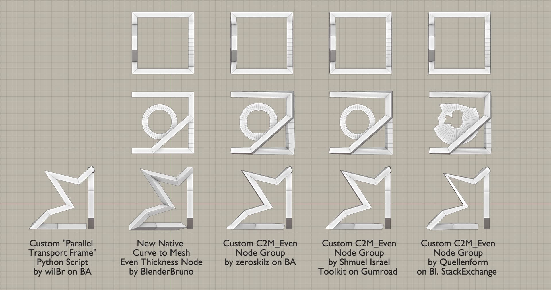
Here my WIP customized parallel transport frame script if you want test it with all your paths…

To use:
copy the script text in blender text editor, select one or more curve/mesh paths and click on
text editor run script button (alt p).

import bpy, bpy_extras, bmesh, math
from mathutils import Vector, Matrix, Quaternion as Quat
from bpy import context


def planeProfile():
    vtx = [ (0.1,0.1,0), (-0.1,0.1,0), (-0.1,-0.1,0), (0.1,-0.1,0) ]
    edges = [ (0,1), (1,2), (2,3), (3,0) ]

    mesh = bpy.data.meshes.new('plane_profile_mesh')
    mesh.from_pydata(vtx, edges, [])
    mesh.update()

    return mesh


#clone profile and adjust location, rotation and shear
def setFrame_profile_byFrame(profile_mesh, frame, pos, scale, sclAxis, bank=True):
    me = profile_mesh.copy() #copy profile mesh to me
    up = Vector((0,0,1))
    
    if bank: 
        q = up.rotation_difference(frame) #or -> axis = up.cross(frame).normalized(); angle = up.angle(frame)
    else:
        q = frame.to_track_quat('Z', 'Y')
    
    mRot = Matrix.Rotation(q.angle, 4, q.axis)

    me.transform(mRot) 
    if scale: 
        mScale = Matrix.Scale(scale, 4, sclAxis)
        me.transform(mScale)
    
    me.transform(Matrix.Translation(pos))
    return me
    

def getPoints(obj):    
    if obj.type == 'CURVE': 
        obj_mesh = bpy.data.meshes.new_from_object(obj)
        return [(obj.matrix_world @ v.co) for v in obj_mesh.vertices] #get path points/vertices list in world space coord
    
    elif obj.type == 'MESH':
        return [(obj.matrix_world @ v.co) for v in obj.data.vertices] #get path points/vertices list in world space coord
    
    else:
        return None


#my customized parallel transport frame
def createSweep_customPTF(path, profile):
    bm_sweep = bmesh.new() #mesh buffer init
    pathsize = len(path)
    up = Vector((0,0,1))
    frame = Vector((0,0,1))
    frames = []
    scales = []
    sclAxis = []

    for i in range(pathsize):
        pos = path[i]
        scale = None
        axisScale = None
        print('pos: ', i)
        print('frame prev: ', frame)

        if i < pathsize-1: #middle points
            if i == 0: #start point
                t1 = (path[i+1] - path[i]).normalized() #calc point forward tangent
                axis = frame.cross(t1).normalized()
                angle = frame.angle(t1)
                q = Quat(axis, angle)
                frame.rotate(q)

            else:
                t1 = (path[i+1] - path[i]).normalized()#catetoA #calc point forward tangent
                t2 = (path[i-1] - path[i]).normalized()#catetoB #tangent backward
                t3 = (t1 - t2).normalized()#hipotenusa
                axisFrame = frame.cross(t3).normalized()
                angleFrame = frame.angle(t3)
                
                n = t2.cross(t1).normalized()
                axisScale = t3.cross(n).normalized()
                angleScale = t2.angle(t1)
                beta = math.pi - angleScale
                scale = math.fabs(1/math.cos(beta/2))

                q = Quat(axisFrame, angleFrame)
                frame.rotate(q)
                #1.41217
                #2 = 1.9465
                print('frame: ', frame, ' scl: ', scale, ' sclAx: ', axisScale)
                print('angleFrame: ', angleFrame, ' angleScale: ', angleScale, ' beta: ', beta, ' axisFrame: ', axisFrame)

        else: #last point
            axis = frame.cross(t2).normalized()
            angle = frame.angle(t2)
            q = Quat(-axis, angle)
            frame.rotate(q)
        
        frame_mesh = setFrame_profile_byFrame(profile, frame, pos, scale, axisScale, bank=False) #create new profile copy for new loc,rot,scale
        bm_sweep.from_mesh( frame_mesh) #append current frame profile to mesh buffer
            
    # end loop to create frames on each path point

    #bridge profiles pairs (2 by 2)
    n = len(profile.edges)
    for i in range(pathsize-1): 
        e1 = bm_sweep.edges[i*n:i*n+n] #get first full profile
        e2 = bm_sweep.edges[(i+1)*n:(i+1)*n+n] #get next full profile
        bmesh.ops.bridge_loops(bm_sweep, edges=e1+e2) #exec brigde edges
    
    return bm_sweep

###########################################################


##========= MAIN ==========##
##=========================##

import time
start_time = time.time()

paths = context.selected_objects[:]
profile = planeProfile()

if len(paths) >= 1: 
    
    for o in context.selected_objects: o.select_set(False)  #deselect all

    for p in paths:
        ########## sweep path ##########
        path = getPoints(p)
        bm_sweep = createSweep_customPTF(path, profile)
        
        me_sweep = bpy.data.meshes.new('sweep_mesh') #new empty datamesh
        bm_sweep.to_mesh(me_sweep) #transfer/convert BMESH sweep path to MESH data type
        bm_sweep.free() #clear memory
        
        sweep_obj = bpy.data.objects.new('sweep_obj', me_sweep) #new object
        bpy.context.collection.objects.link(sweep_obj) #add to scene
        context.view_layer.objects.active = sweep_obj #active
        sweep_obj.select_set(True)  #select
        sweep_obj.show_wire = sweep_obj.show_all_edges = True #show wireframe over shader
        
        print("--- %s seconds ---" % (time.time() - start_time))
2 Likes

Hi… For my node-group, when using Beziers you need to add a Resample set to Evaluated first… That’ll make the results more consistent with the test-case.

The reason why it doesn’t do that by default is because the base node is used in a curve sweeper node which allows the user to sweep points to generate curves and you may want to preserve minimal Beziers when doing that.

@BlenderBruno: The math used in my node-group is pretty simple and discussed here.

Thanks

2 Likes

It also helps to use Z-Up normals, although that does create weird twists in vertical sections.

1 Like

OK, @zeroskilz, thanks for your input. I also tried to use the Z-Up but faced the same twisting issues. Now the algorithm pretty much builds up custom normals in order to keep the profile from twisting at all between curve elbows.

2 Likes

Z-Up does that, but that has nothing to do with even thickness. The “even thickness” toggle should just be ensuring even thickness… it should not be doing anything to the curve normals/tilt… I would expect something which affects the curve tilt would be included in the Set Curve Normal Node as an extra, separate option.

E.g. here is another potential option which is useful for arch-vis for curve-to-mesh which has nothing to do with curve-tilt or thickness:

…making the point that you should not be conflating even thickness with tilt and maybe keep them as separate concerns.

Good luck.

1 Like

You’re right, Z-Up does not do much good to Even Thickness, I was just referring to it regarding my experimentations.

Personally I prefer the term Miter Joints for my method as it is really mimics the real world woodwork for crown molding or picture framing. So far the consensus is leaning towards the more broadly understood Even Thickness term though! And I agree that it makes the Curve-to-Mesh ignore the Normal Mode. Note that the tilt can still be tweaked per control point though.

I guess that technically a Miter Joint option that’s actually changing the normals would make sense in Set Normal Mode node however it is so much linked to the profile extrusion that it does not make sense from a user stand point (can you think of a Geo Nodes use of Miter Joint Normals without Curve-to-Mesh?). Also, if Miter Joints was set on the Set Normal Mode, it would ignore any Even Thickness checkbox on the Curve-to-Mesh node… oh well.

Without complicating Blender too much, it seems reasonable to solve most problems with a single check box Even Thickness. More specialized Geo Node groups like yours should satisfy specific cases.

BTW, I noticed some twisting in your Curve-to-Mesh Even Thickness node group. Is that expected?

2 Likes

Yes - Profile instancing:


Currently it is a very iffy thing to do in conjunction with Z-Up and it would be nice to have access to traveling frame normals.

Again, they’re not necessarily related.

Yes - in the setup you have it is by default following the “minimal” twist method. Switch off the even thickness to let it default to regular curve-to-mesh and you’ll see the same twist. The twist isn’t coming from my node-group - it’s coming from the curve.

5 Likes

Thanks @zeroskilz, I get the Profile Instancing use case. Now for that problem, the Normal alone is not enough because of the non uniform scaling (shear against multiple axii) being applied by the Miter method. In order to achieve proper Profile Instancing, the Set Curve Normal would need to produce the normal (forward basis vector) as well as produce the “Cross” basis vector necessary to properly transform the profiles at each elbow (bottom line, that’s a full transformation matrix!). This is what’s happening in my approach but is not exposed at the moment.

They are in the sense that the Miter Joint method is by design imposing an even thickness so if set in the Set Curve Normal, it would always negate the effect of a more general “Even Thickness” checkbox in any downstream Curve-to-Mesh node, making the node setup confusing (as a general user experience, better keep to a minimum the conflicting features if at all possible).

Got it for the twist :slight_smile: thx.

1 Like

Ah yes, this is also what I did with an experiment to achieve varying profiles along a single curve. It didn’t work out, haven’t pushed it further but the reasoning is sound (without matrices, that is)

1 Like

I’ve been struggling to make neon signs actually.

Would this patch help out? Could you share some of the issues you had (screengrab or video?)

Awesome stuff! This was one of the most important modelling features still missing in Blender, so thank you for tackling it. :thumbsup:
As for the limitations you listed, I think they are expected when working with this type of geometry. It’s probably best to to let the user deal with it manually, rather than disabling cyclic by default. One thing that could help is to turn Use Miter into a field input, so that the effect could be controlled on a per-vertex basis.

Also this might be unrelated, but do you have any plans to address the shading that Curve to Mesh node creates? Right now if you want to have smooth shading across the profile, but sharp corners, you need to apply the modifier and manually set corner loops as sharp. If Curve to Mesh node could output corner edges as a selection, then shading could be fixed inside Geo nodes, thus preserving procedural workflow.

2 Likes

Thanks Slowburn, good feedback! I’ll incorporate it in the ticket. So far, I haven’t looked at the shading or “per ctrl point” control of the effect, I will try to take a peek at that… though it might be difficult to put in place because the “Miter” effect involves at least 2 curve points (basically at least one segment!) so controlling it at the point level may not make much sense.