Troy,i think this is the housemade problem with Filmic and TCAM V2.As clever it is to desaturate the color towards the whitepoint with increasing value,it mangles the color as you always say.
If you want to keep some colors saturated as is,then you have to change the method somehow.
You know the classic 3 shots with 2stops + and - from EV0 and combine them in your graphicapp.
I think as old it is.it is maybe a good starting point.As idea,keep the important midtones at EV0 and blend in at overexposed data from the -2 shot ,that has its bright colors you want.
I now this sounds maybe to simple but you use the colors as there are shot or rendered,and you want that right?I mean you have the datas you want in the shot stored.Except even the HDR shot is clipping ofc.
Now its up to you how to make use of the data,hehe.
And another idea,if you want to make use of the full range of maybe 16 stops.I would do the classic -2 for the main colors within 2 stops,and useing filmic at the pixels that going above the 2 stop.this way you can keep some bright colors,and everything its way above get the filmic desaturation curve.
You miss the point; the medium is limited. You simply cannot express the range, and the range isn’t what is important in the first place.
But feel free to give things your own attempts at image formation. It will all become very clear.
Probably going to be tricky to design something when a definition of “bright colour” is the question at hand. By definition, this attempt would darken things in a rather surreal manner.
Sure we know that we all looking TV on LDR or the monitors,even in cinema the projection form the film.There was a statement ,if you can make a photo from it,you can render it.
Have this changed?
Tbh my postings are just ideas what came to mind,maybe there are useless or maybe you get a new idea from it,thats all.I think you have read almost all new paper from this tonemap topic?
If we can,help us to help you, to get brainstorming better ideas.
The thing is, it is impossible for the medium (your monitor) to have high intensity and still saturated color. If you try it you will end up having the “Notorious Six”.
Even if you have a medium that can do it, the question is “Do you really want to lose the ability to overexpose things?” Just think of how overexposure has been such a creative tool for artistic purposes, I think overexposure is a very important part of the artistic side of image formation.
Considering both the limitation of the medium and the artistic situation I believe path to white is already the most sane solution here.
I don’t know if I understand this. A photograph in the film sense, formed an image. A photograph in the digital capture era is not a formed image, and rather a capture of stimulus relative to a digital observer sensor. I see them as quite different things, hence why I don’t quite understand the statement?
Of course not! I have read more than a few, and the few that define “tone” seem to be solely focused on the idea that luminance forms all of tone, which I currently do not believe is correct.
I couldn’t applaud this framing any more! This is precisely one of the facets at work here. I’d go so far as to even say that the term “overexposure” is a tad of an overstep!
When we use subtractive mediums, there is literally no “overexposure”; we vary the depth of a filter against some constant illumination / projected source. That is, what we see is a continuum from maximal filtration blocking (projected creative film) or reflecting the filter (paints) to minimal / no filtration. It’s a continuum here, with no clearly defined “overexposure”.
With that said, I completely agree with your summary. Perhaps this is why image formation systems that equate image formation with an emulation of the human visual system fail rather profoundly? Not sure! Still learning!
Note that in this case, we could describe a “path” in terms of colourimetry xy coordinates. It could answer whether a given chromaticity march in a straight line path to achromatic?
I don’t believe that the discussion of subtractive-inspired mediums implies a “path”, but more specifically addresses an appropriate “rate of change”.
In the blue sphere example, we have a number of things going wrong. Of course, we can say “the illuminating light should be peak display achromatic!” But that feels like only a portion of what is going wrong here.
If we look at how the result, which is basically some “curve” applied to the source tristimulus blue channel, we can see a deeper problem. Sure… we will likely escape the range of the medium’s blue emitter, but also pay attention to the rate of change of the blue! It goes through regions that do not properly communicate, as best as we can guess, the rate of change of the illumination across the surface. The other interesting facet here is that this rate of change varies in terms of purity and hue angle; if we did this with a yellow light source, applied precisely the same curve, we’d end up with a different apparent rate of change!
This is why my personal, completely irrelevant and anecdotal belief is that if we are trying to crack this spectral image formation nut, it requires disentangling whatever the heck brightness’s relationship is with hue and purity.
I hope we are able to, yes. There are a few things to iron out first, and of course there’s a good chance there will be some challenges which will come up after getting a review from the Blender devs, but a lot of the core features are in place, there’s just a bit too much bugginess for it to be acceptable at this stage.
Yep, @pembem22 has done all of the hard work in migrating it over to Cycles X.
I’ve been doodling away with spectral rendering with Blender a bit, by just making a script that renders an image at certain wavelenght steps and changes the material refelectivities and the light power to match the spectral reflectances and the distribution for that particular step.
Which results in a number of exr images which then can be summed to represent the spectral image where every pixel contains a power distribution over the wavelenght steps. This then multiplied by a sensor spectral response results in the rgb primaries being obtained for that particular sensor.
However, this all seems horribly inefficient, essentially the raytracing is carrying a single wavelenght instead of the spectra and for each wavelenght step it is being re-done, instread of instead of rgb triplet, the rays “payload” would be the spectral distribution, reducing the render time to more or less same as single image rendering time. (instead of rgb value, it would be a trivial list of values).
I stumbled upon this topic and it seems extremely interesting, and impressive, however the thread is quite a beast already and it is difficult for me to grasp what the status of the cycles spectral renderer currently is.
Is there a tutorial or description somewhere that would highlight on how the cycles has been modified to support the spectral rendering? What is the method used, has it been modified to carry the spectra instead of a triplet, or is it more like the solution i’ve dabbled with?
There are couple of publicly available datasets that have some material reflectances and illuminant spectrums along with the camera spectral responses. like: Etsin | Research Dataset Finder which can be used to simulate and compare. There are relectances of the Gretag-Macbeth chart primaries there and raw images from devices under measured illuminants taken with the chart in the image, so it can be used to compare the render to the real thing.
The process you explained sounds a lot like how I started with Spectral Cycles; drivers, scripts, and monstrous compositing networks, and you also came to the same conclusion, that rendering individual wavelengths as whole images is highly inefficient.
Apologies for the monstrous thread, it does cover a lot of tangential topics.
The implementation of spectral cycles is probably about what you expect; converting a few data types from vec3’s representing RGB weights, to vec4’s or vec8’s representing wavelength intensities, and some logic on either end of cycles to generate those wavelengths, then to composite them into the final image. There are a few other important aspects to it, which I’m happy to describe if there’s anything in particular you’d like to know about.
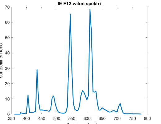
I guess first pops into mind: why vec8 only? Some illiuminant spectrums are extremely spiky,
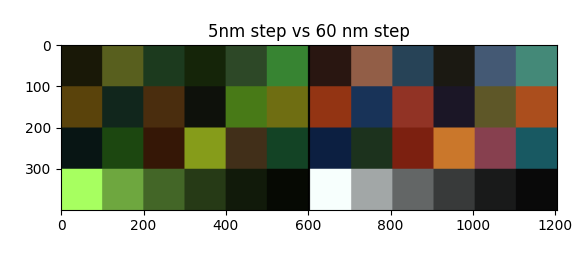
Like this IE F12 for example. I would imagine representing this only with 8 steps would result in somewhat crude representation, resulting in some error. I did a quick simulation by using the spectral distribution of that illuminant and the reflectances found in the same dataset, here is a comparison between 5nm step and 60nm step:
The vec8 version looks almost like whitebalanced already … the more accurate one is on the left, it has not been whitebalanced yet so it just shows the sensor raw input. I used the canon5dsr sensor spectral response here to convert to rgb triplets.
I wanted to post the spectra of IE_F12 as well, but it seems i can only post one media per post, i’ll attach to next one
Good catch. The 8 wavelengths are per-ray, and differ between rays. This results in a uniform sampling of all wavelengths in the configured range, using the same monte-carlo sampling method used for material properties, DOF etc. This means we get the ‘ground truth’ result after many samples, as opposed to the ‘binning’ approach which will always have an error in the spectrum sampling.
The 8 wavelengths here represent one ‘hero’ wavelength which is used to determine the ray path, and 7 secondary wavelengths which just compute their transmission rates along the same path. Each ray has a new hero wavelength and it’s 7 secondary wavelengths.
If you’re on Windows and the build gods are happy today, I will have an windows build of it some time in the next few days (hopefully in the next few hours) that I can send you. Note there’s still some bugs and missing features. You had very good timing, as I just started looking at getting Blender building on a new computer.
Can I also have a link to that when it comes? Or maybe update the Graphic All page? The build I have now is still when Geo Node Field build was a separate thing from Cycles X build so I have been unable to test files built with 3.0 geo node.
Yep, I’ll upload it to GraphicAll. I’ve been having some troubles with the dependencies (I’m currently on attempt 2.5 to download all of the 6ish GB of dependencies at 0.125 MB/s ) but once I get a build successfully and make sure it’s usable, I’ll upload it.
I’d like to finish off the last little bit of work so we can start the review process, it has felt so close for so long.
 ?
? ) but once I get a build successfully and make sure it’s usable, I’ll upload it.