Here a paper of determination of complex refractive index from reflectance at normal incidence
Nice find but this requires measurements at two different angles (one head on, one slightly off), as well as with known polarization. I’m pretty sure that we can’t really do better than taking that formula for n as our estimate. It’s really a matter of degrees of freedom: If you’re looking for two values (per wavelength), you’re gonna need two values (per wavelength) to get them.
You can not compare a n k=0 with a complex nk conductor equation.The reason is that with the conductor eq. and a k value for absorption,the higher the absorption gets,the more the F0 is reflecting (usally around 80% for aluminum ect).
If you have a IOR without k,you have a material without absorption coeff.like dielectrics.with k=0 you never get a F0 that high,usally around 3-5% for most dielectrics.For this reason,usally with dielectrics a conductor equation is not used.
Fair but these pure RGB spectra are nonsense anyways. No actual material has these spectra.
I guess I could try again but with the colors set to that range (so like R .03 G .04 B 0.5 or something) giving something that’s perhaps more realistic
Or wait are you saying there’s a different kind of equation to use in this case?
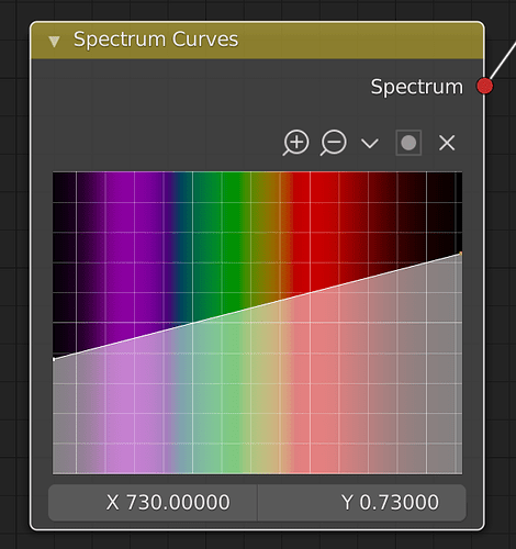
I wonder how the spectrum node is working.is it a weighted summerized to RGB values?
Tbh i am not sure(at what point its a dielectric/semi/conductor with k,its not allways classified),i have read that the equation for conductors,because of its opacity properties are different to dielectrics with k values.
With dielectrics and k (absorption coeff) you have a beer lambert absorption in a volume,it could be semi transparent like colored glass.
it’s just a lookup table. The renderer now basically picks a wavelength according tho the Hero Wavelength algorithm and then looks up the spectral response of that wavelength for each material it encounters.
Only at the very end, when the color is being committed to the render result, is that wavelength turned into a threedimensional version that regular images store. Anything in between now happens as individual wavelengths (as it ought to)
“Medium Contrast” currently seems to not work correctly? - It looks like that always renders in “Standard” view transform (which now doesn’t exist. I take it that’s “Display Native”?)
Normally “Medium Contrast” would behave exactly like “None” (which still works now)
I’m also missing the “False Color” view transform which is useful for checking which parts of your scene are too bright or too dark
@kram1032 These are issues with Blender’s update to OpenColorIO v2, and not an issue with the spectral branch specifically.
ah good to know, thanks
Hi all, so many things to do. I hope my update frequency is any good enough  .
.
Okay, I have moved all parts of the big scene into separate scenes. You can download the blend here: https://we.tl/t-kuH4BBu2or . It is set for 50% size and low samples/pixel for ease of use and the descriptions are missing, but, it is all a bit better defined now, and, renders much faster if you need a specific test.
@smilebags: If you need updated descriptions, please let me know. Also, if there are specific properties of Spectral-cycles you want tested, I can make dedicated scenes as well. I suppose the file will grow with each additional request. For instance, I’d like to compare various light sources against each other: Wattage, area, direction, et cetera. Any ideas about that?
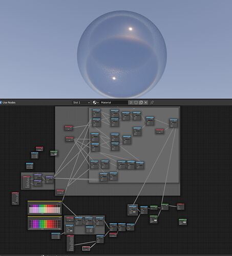
I have tryed to build a simple reflection and absorption of a dielectric material,based of nk,in this case water.
Notice this is without any angle,just the R0 to get a start.I found this method before, and use it in my carpaint shader.
I think i found a bug in the spectrum nodes.The k values are so small IE at 450nm blue the k value is 1.0200e-9.I have tryed to write or paste the values into the spectrum node,but it has only 0 stored.
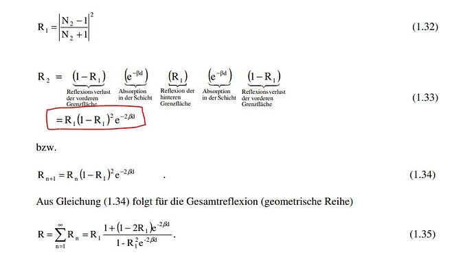
here a excerpt from the paper where i found the method.
the first build,with sky tex as light.
and the paper
Material_Festkoerperoptik (uni-wuerzburg.de)
edit,i added a dielectric fresnel equation to it.
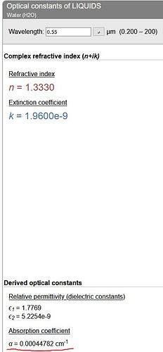
edit,I have rechecked if the refractive index site is using the same equation, to get the absorption coefficient.
As you can see at the screenshot from the RI site that at 0,55 micrometer you get a alpha absorption coefficient cm-1.
Then i checked the result in openoffice calc.I got the same number but have to scale it from micrometer to cm with multiplying 10000.For meter 10000*100.
here a preview with cycles spectral,dielectric water with reflection and absorption at 5.9 m
You can download the shaderbuild for try at blenderartists,here
you could try this with the correct spectra for at least one version of the color swatches as I posted above
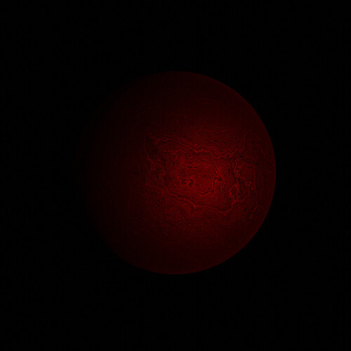
I have copyed the nk spectrum from the iron oxide,and the absorption is …red ![]()
here with 3micrometer absorption.more than this and its get black.
I tried simulating thin film and I think I hit a snag. It seems to almost work. There’s just one extra thing I’d need, and that is the cosine of a spectrum.
Since we have exponentials and logarithms it seems to me like that would be a logical addition.
As far as I understand, I’d have to be able to do the following:
// Starting point:
// Wavelength: λ
//// Three (possibly complex) IORs:
// n₀: Outer material (usually air, so n₀ = 1)
// n₁: Thin Film Material
// n₂: Inner Material (if it's soap bubble, this will usually also be air)
// (DO THE WHOLE COMPLEX IOR SPIEL TO GET:
// r₀₁: The reflectance from the outside material off the thin film material
// r₁₂: The reflectance from the thin film material off the inner material

// Given the transmission angle α of the outer material into the thin film
// (i.e. cos(α) = Incoming · Normal),
// find the cosine of the reflectance angle β from the thin-film material
// off the inside material. Call it cβ. - this depends on (the real parts of) n₀ and n₁

n₀₁ = n₀/n₁
cβ = n₀₁ * sqrt(1- n₀₁ sin²(α))
// This assumes the coating has the same normal as the underlying material.
// If they may differ, something more complex is necessary.

δ = 4 * π * n₁ * cβ / λ + Δ  // if n₁ is complex, only use the real part
// Δ is a parameter that's a possible phase shift between -π and π
// some material interfaces apparently cause this
// δ is wavelength dependent as is β so I need a cos of spectrum.

t₀ = r₀₁² + r₁₂²
t₁ = r₀₁ * r₁₂
t₂ = 2 * cos(δ) * t₁ // another cos-of-spectrum

R = (t₀ + t₂) / (1 + t₁² + t₂) // the actual final reflectance spectrum we're after
That should be all. Honestly, once the complex IOR bit is figured out, this wouldn’t even be that tough anymore, I think
Blenderartist JettG_G has allready rebuild prusters OSL thinfilm shader, for GPU use in Cycles.
As sayed before i have done a dielectric thinfilm shader build for Cycles too.
Right. But this is about how to do it with spectra.
I get that you can use this to three-wavelength-approximate thin films and be backward compatible with regular Cycles just like it’s possible to three-wavelength-approximate complex IOR materials in regular cycles.
And it really looks quite lovely. (Also, nice HDR with that floor lol)
I’m saying, however, that the above is how you do it without that three wavelength approximation.
Sure,i think instead of the tri-chromatic color vec, you want to use the spectrum nodes.You would need however a lambda for the phase equation,for calc the wavelength inside the thin film layer.
the lambda is easy enough to get:
Here I take as input the wavelength in nanometers and as output the wavelength in micrometers. Just a linear spectrum. - It’d be trivial to change this to any other sort of units I might prefer.
The only difficulty I see is the cosine / sine of a wavelength which, as far as I can tell, I can’t currently obtain.
