@brecht is the colour stored in either eval or sc->weight depending on whether you are sampling or evaluating the BSDF? It seems to be, but I’m not sure if this might be what is causing my confusion when it comes to converting behaviour of lights and the metallic component of principled to spectral.
This paper explains a method of generating MIS weights for wavelength dependent scattering functions. It utilises hero wavelengths.
Most materials are not wavelength dependent in the spatial domain, meaning paths for all wavelengths could be calculated just once and then sampled at many wavelengths. Materials that are wavelength dependent in the spatial domain - such as ones showing dispersion - could be either branched or sampled at just one wavelength.
I believe I now understand the reasoning behind not wanting wavelength to be exposed to the user when creating materials - if that is done, optimisations around attaching more wavelengths to a path cannot happen as easily. I think adding a property to shaders such as wavelength_dependent would allow for some nice optimisations to be done down the track, such as sampling the scene as far as can be done without wavelength dependent paths, then sampling from the last (wavelength-dependent) shader at many different wavelengths. If shaders are not aware whether or not they are wavelength dependent, such optimisations can’t be made.
@brecht am I on the right track with the reasoning behind your resistance to exposing wavelength to the user?
No, it does not depend on that. Both values are always multiplied together. I guess you are just not handling conversion for the combined result in every place where bsdf_eval or bsdf_sample is called.
Yes. For various optimizations and bidirectional rendering algorithms it’s important for the wavelength not to be fixed in advance.
Just a quick note that I’ve implemented the reflectance recovery methods with Rec. 2020 and XYZ spaces here. Also addressed “real” object colors in these spaces.
1 Like
@brecht How should I generate the random numbers for the wavelength? I saw in kernel_random there are some what looks to be useful functions, but when I attempted to use it, Blender crashed.
Regular Cycles: 4m50s, considerably lower noise and fireflies.

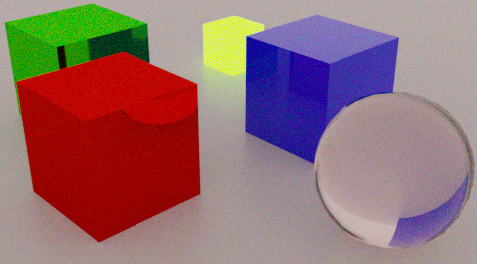
Spectral Cycles. 5m21s, More noise and colour shifted. Optimisations can be made to reduce noise without increasing render time, and the colour shift seems due to an issue with my number generation.
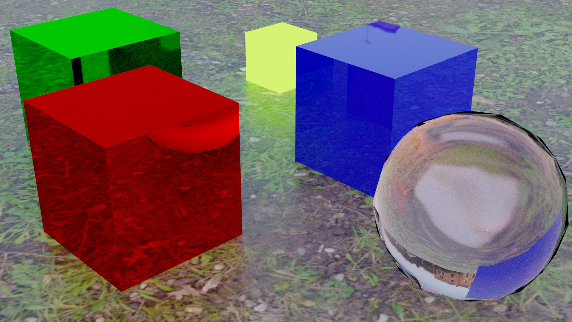
Verification test: testing visual differences between my build and regular cycles. It seems there’s still some issues with sampling, because white light sources show up a little too pink. I have tested this without image based lighting with the same result, as can be seen here:
How are you upsampling the RGB or are these spectral feeds?
How are you going back to RGB? This mustn’t be hard coded an instead should rely on the XYZ role, or better, use an XYZ view transform and simply leave the buffer as XYZ.
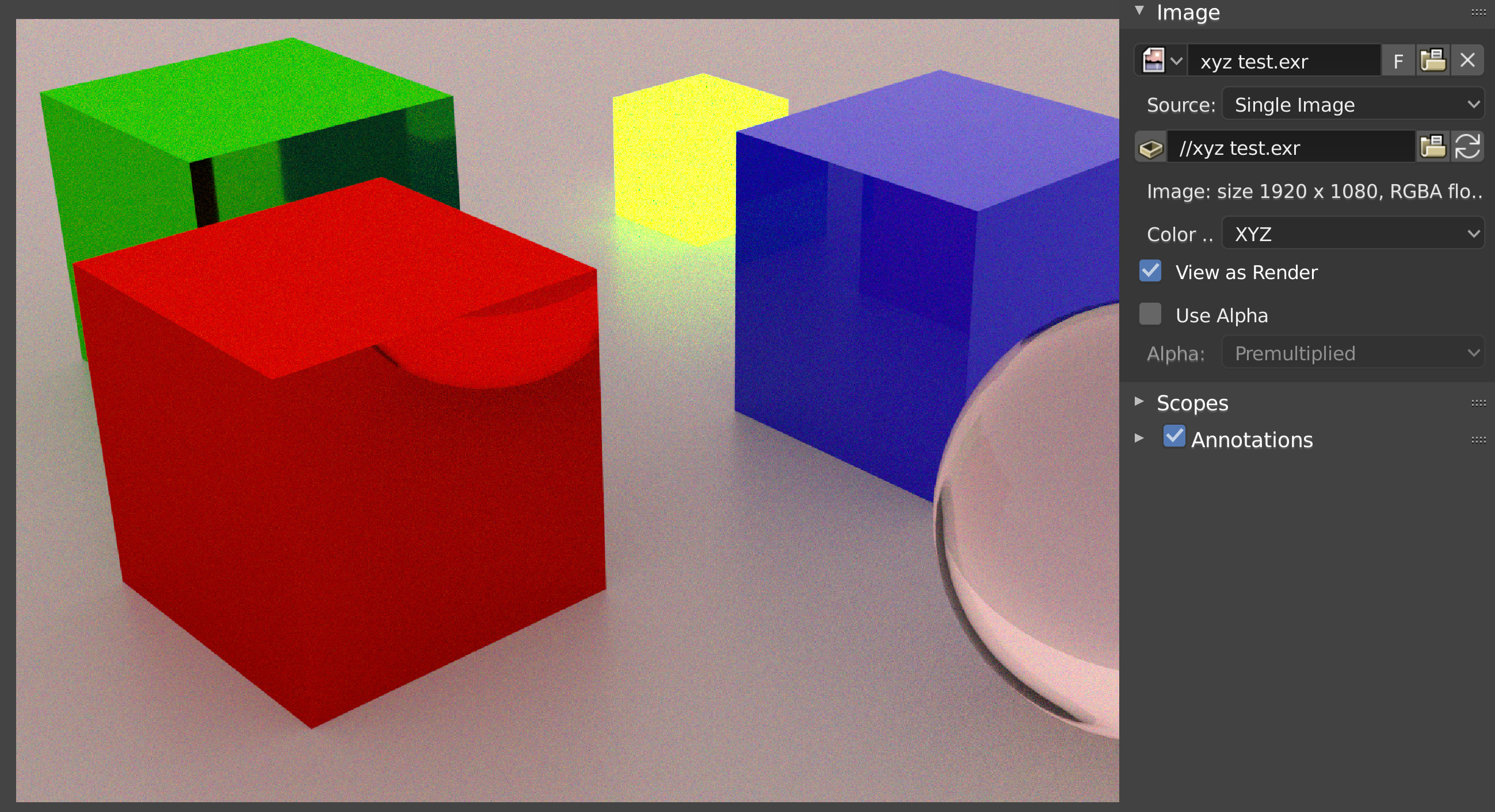
The light source in the third image (which still shows the tint)is a flat 1 across the spectrum, making it an E illuminant. The second image (upsampling with the REC.709 to spectral tables from Burns in this thread) has the same cast, which would suggest it is either an off-weighted sampling problem, or the final spectral>XYZ>RGB conversion which is off. I’ll make another build and leave off the XYZ to RGB conversion, to see if I get the right XYZ coordinates for the environment.
What do you mean by XYZ role? I think the best solution would be to leave the data in XYZ and as you said, use a view transform to handle display. Though, would that mean that the user gets given XYZ data in the compositor? That might be rather unexpected.
The scaled versions would be incorrect I believe, as they give too much say to the blue and green primary.
Feeding the scaled version of the Burns curves to an SPD of 1. will likely result in the wrong colour, which should be easy to confirm via Colour. If you use the unscaled variant and 1. across the board, you’ll get D65 I believe, as the unscaled versions closely match the CIE xyY coordinates per primary.
There’s two ways that one could go about this via OCIO. The first would be to summon the XYZ role which is essentially an alias per configuration. @lukasstockner97 recently added a commit which adds this role.
The other method would be to convert to three light XYZ, and put the appropriate transforms into a view, along with appropriately sculpted looks. XYZ in reference is still a three light model, and as such, it doesn’t make much of a difference compared to generic RGB. It will behave as differently as REC.2020, ACEScg, etc. would.
Definitely not a fan of hard coded reference transforms. It’s a recipe for badness.
How do I find unscaled spectra for the REC.709 primaries? What does unscaled suggest?
This is true, but if the compositor is fed XYZ data, the user might be a bit confused why the channels don’t behave how they expect - changing G (aka Y) would influence luminosity more than it would in RGB, etc. I think for this to be a suitable and un-disruptive change to Blender, the data coming into the compositor should be REC.709. How we get there is another question.
I agree. I’m sure there are much better ways to do this. What do you suggest as an alternative? Generating a spectrum every time a closure evaluation occurs is likely to be a pretty significant performance hit. The way it is now, I have REC.709 primary intensities and 3 wavelengths as input, and I output the intensities of those 3 wavelengths based on the primary. How I get to those intensities, again, should be able to be switched out, but for now, the fastest and most accessible method is simply looking the values up in a table and summing them together.
I believe Burns has the non-normalized versions on his site.
This is already the case with every darn colourspace out there. Get used to it.
Nope. Hard coding things is junk. Pure junk. Blender already has an arbitrary reference space for rendering assuming the rest of the fixes land. Doing what you suggest is a monumental regression and absolutely backwards in 2018, with HDR and wide gamut consumer goods from Apple and others everywhere.
I’ll take a look.
I’m completely happy with it, I think that most users who don’t understand colour space will be reporting it as a bug if it gets in, though. If, for example, the compositor ‘Render Layers’ node (or whatever it is called) allowed you to assign the profile of the incoming data, this wouldn’t be an issue.
Fair call. I’m not up to date with what changes are planned, so if you have any links to where I can read up on it, I can plan my system accordingly. I’m basing my decisions on what Blender currently behaves like, which might not be how it will behave in 2.8x. Any links to the proposed/implemented changes regarding colour management?
Again, I don’t use “tables” to generate reflectance curves. They are algorithmically generated. Some people may be tempted to compile tables of the generated results, but that is not what I propose.
I think the source of the color shift may be a misunderstanding of what my methods create. For a given color space (e.g. sRGB) and reference white point (e.g. D65), I create object reflectance curves, not SPDs. In order to interpret the perceived color of that object via an SPD, the reflectance curve must be multiplied by the reference illuminant.
I use normalized primaries, as per the standard methodology for converting XYZ to RGB.
Apologies, that was a wording mistake. I’m using the set of values representing spectra with the same colour as the sRGB primaries.
I think I understand that. What is suggesting to me that I’ve done something wrong is that a perfect reflector under an E illuminant is giving that colour. Ill have to look into what stage is wrong, but I believe it is with my code not the implementation of emitters. An E illuminant should give XYZ 1,1,1 if converted, right? Or is that assumption wrong?
Yes, theoretically.
My computations use 10nm interval spectra, so some discrepancy is expected. I actually get XYZ = (0.9997, 1.0000, 0.9992) from an EE input. (1931 Standard Observer CMFs)
Looks like I’m getting the right XYZ values, so I’ll either have to review the XYZ to RGB step I’m doing, or just delegate that stage to OCIO, which would be optimal. Unfortunately I’m not quite sure how.
Maybe there’s nothing wrong with the transforms after all. I tried saving out the XYZ data then using OCIO to do the transform into RGB, and I’m getting the same appearance. I just didn’t think E illuminant would be so saturated relative to the D65 white point. Supposedly when X=Y=Z, this pink is the colour you get in REC.709.
I will have to try again after I implement different base spectra for emission.
(Corrected: in the original post I forgot to gamma correct the linear rgb to get sRGB. Corrected below.)
D65 is bluish compared to EE, so it makes sense that EE would be reddish compared to D65. I compute it would appear in a D65 referenced environment as sRGB=(255, 229, 225):
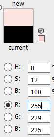
Indeed it does. There’s nothing wrong there after all, now I just need to program a sensible and easy to use way of defining emission spectra.
a profane question, theoretically the functionality of the spectral render could also work on eevee or the calculation request is too expensive ???