In good old times, there used to be some really crappy renderers, such as Thea renderer, which implemented much more primitive reflectance model, which did not model microfacet reflection, and then they compensated for that by adding some arbitrary “Micro Roughness” parameter to the UI, which would fake the effect by changing the glossiness amount on the grazing angle. So in the end, the users had to control much more buttons to ultimately still reach inferior quality.
The reason you came to the conclusion this effect doesn’t happen out of the box in Cycles is most likely that you failed to correctly reproduce the conditions you observe on the photos in your 3D scene, or you expect the effect to be unrealistically strong in the conditions which would naturally not make the effect very obvious.
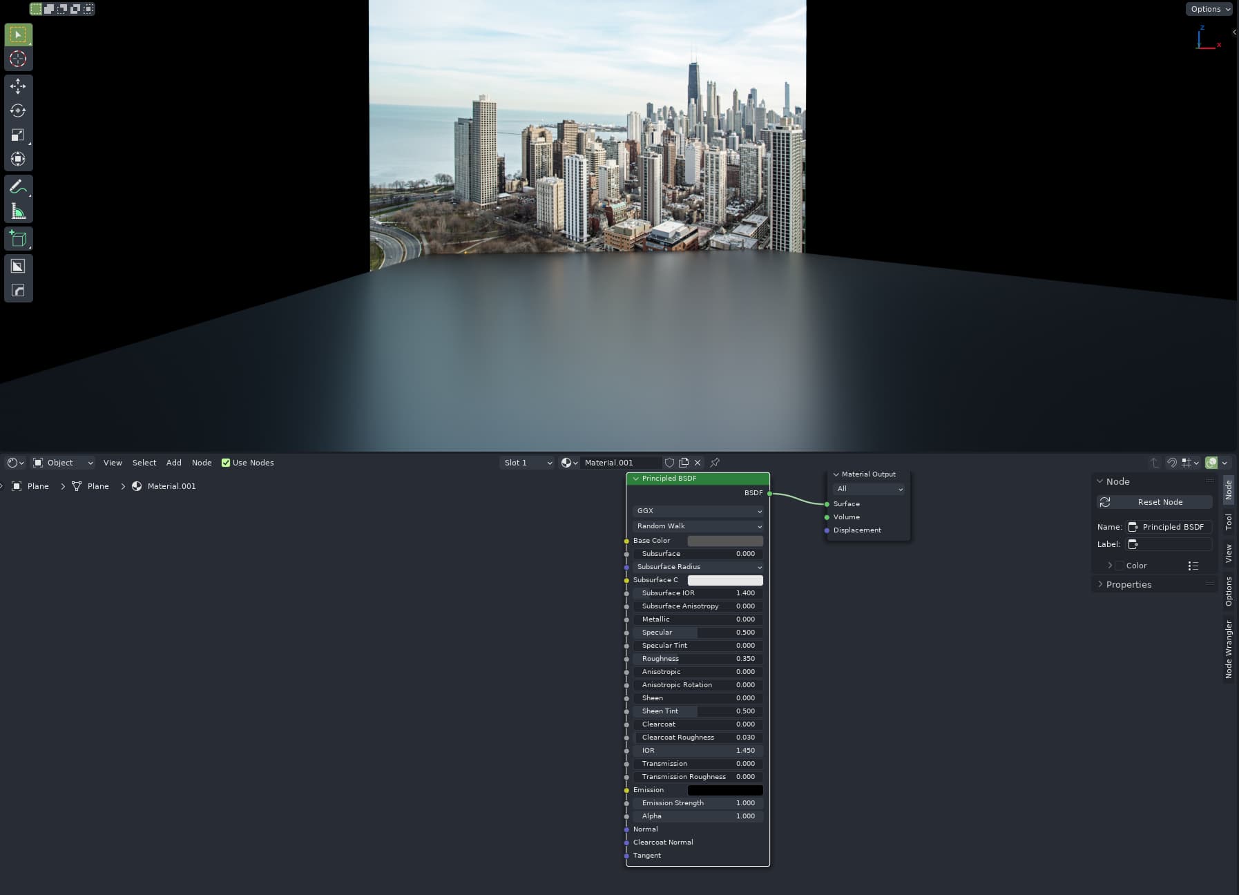
At the first glance, the image looks almost similar, but the effect has disappeared. That’s because the background image plane is no longer touching the end of the glossy plane. Instead, it’s much, much farther away from it and much bigger.
People often misunderstand how the microfacet reflection is supposed to work, and then make assumptions about its absence.
I am not sure if that bug is related. Non the less, to create conditions to reproduce that photo, you should do following:
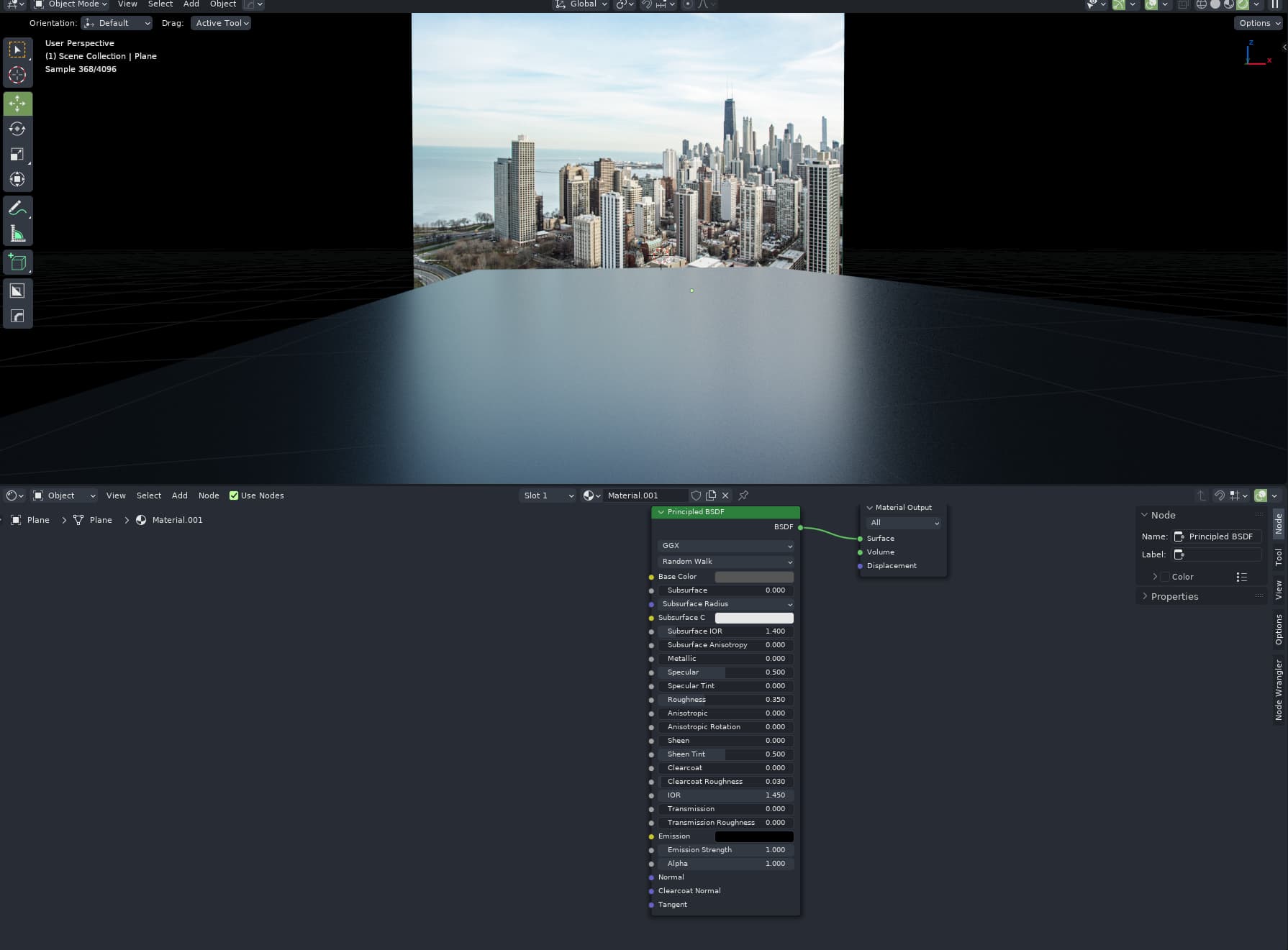
Make sure the end of the leather surface is close to the source of the light, like on that reference photo. It appears that the leather cover is literally touching the lit curtain, so the reflection starts at the contact point of the reflected content, curtain pattern in this case.
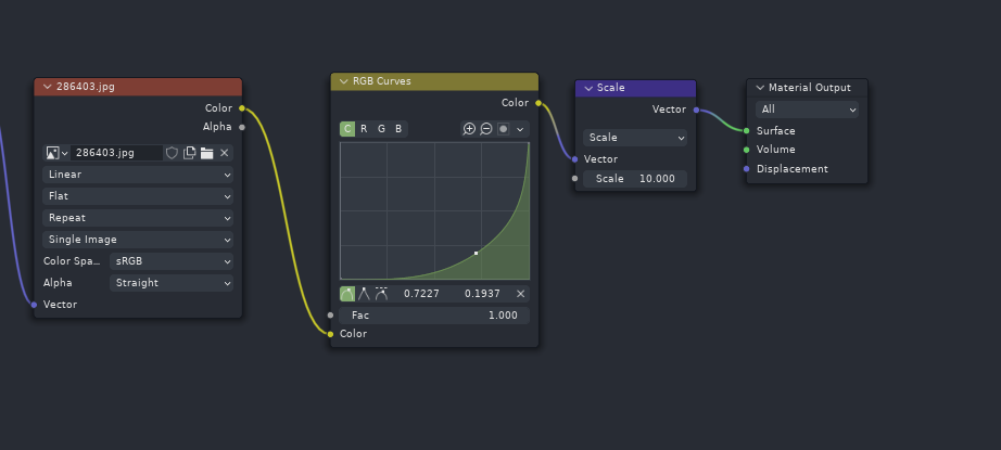
Make sure your light source has sufficient dynamic range, and therefore contrast. Putting in an emissive JPG on a plane won’t work, since real world has much wider light dynamic range. Either use HDR image/raw format photo, or in my case, I faked it by using just low dynamic range JPG, but extrapolating it to HDR using curve and multiplier amount:
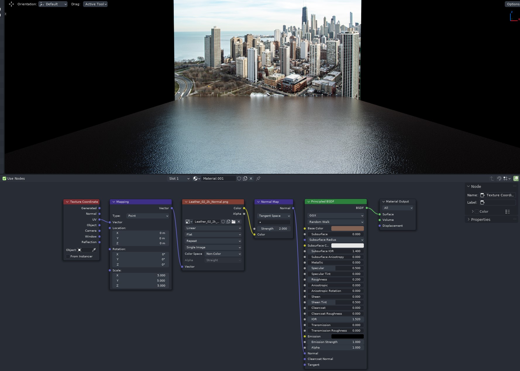
The effect on the photo can be more pronounced if you combine the micro roughness (just the right value of the roughness amount) with macro roughness, which would be a normal map or bump map. The idea here is that the macro details, such as the leather structure and scratches visible by naked eye will further vary the direction the reflected light is scattered in. So a normal map with fine structure will allow you to reduce roughness a little bit more, and get even more contrast between roughness at the contact point and roughness further away from it:
We did discuss this, it would make sense support recreating the principled BSDF using individual components. However it’s unlikely to happen immediately along with the initial principled v2 implementation.
If we do this, it would not be a node that still combines dielectric reflection, metal reflection and clearcoat into one. Rather you would combine 2 dielectric BSDFs and 1 metallic BSDF, likely using a new layer closure node as exists in MaterialX (and which was added to OSL just this week).
Actually, it came from production rendering at Disney. The idea behind it was to easily mix between different types of materials and have a plausible transition. I think that principle actually helps usability in tools like Substance painter, besides also just saving memory for game engines.
This sounds very odd. Holo stickers don’t sound like anything which would require faking with the current Principled v1 model. Do you have an example of what you wanted to achieve?
Thx @lukasstockner97 , considering you’re planning separate coating node with IOR control this is ok, I guess.
My only concern is that glass, plastics and oils have IOR closer to 1.5 indeed, but water has 1.33 and alcohol about 1.35 so they will give different reflection curve. I’m not sure if not having this control in main node affects usability or simplicity so much.
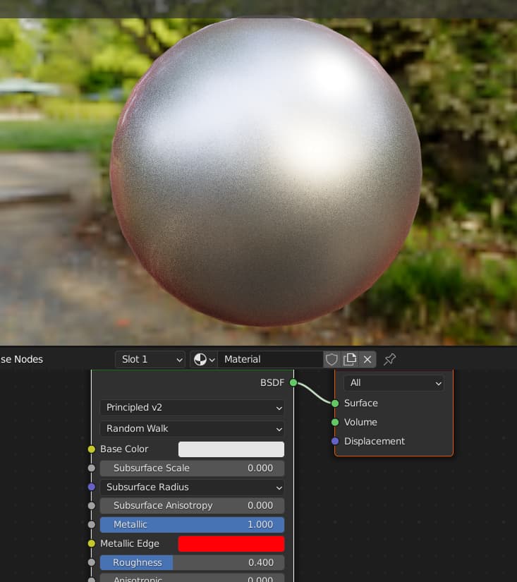
Just downloaded the latest build and I wonder why the Metallic Falloff is removed? Now the metallic edge falloff is on a constant value with no control over?
I’ve also just installed the latest build, and as soon as I set Cycles as the renderer (GPU mode) and set the Subsurface Scale to a value higher than 0, I’m getting this error:
It would be really nice if these example values for metals become part of the documentation for V2. And further maybe a link / description how to use real world data with this model - in regards to the link from the patch comments (https://refractiveindex.info/)
I wonder why there is no SSS color.If you want to simulate eg. deeper bloodvenes then you usally have a map for it, which is not visible in the basecolor map.
And the scale makes only sence if you want to fit the scale of a SSS to a model.I think this is a wrong way.
The scale of a model is usally chosen by import or by creating the model.Then the artist should fit the SSS radius to the scale the model has.
Then scale should be a blend mode,to blend the SSS from 0 to full SSS as blend value,not as scale,if that makes sence.
Basicly you want how much SSS,which color,and how deep.
About the microfacet Fresnel.I hope this gets implemented .This is a subtle needed improvement to more realism.
The legacy SSS color was just to be mixed with the base color with the scale as a factor. So if you want the previous behavior, just mix your map with the base color, it’s intuitive.
In other words SSS has always been using base color, it’s just that the system before would mix another color into the base color, with the mix factor also being a strength scale. So previously if you want to change the strength of SSS, you would “accidentally” change the color mixing, these interdependencies made the SSS in the previous Principled BSDF super confusing.
That’s the limitation introduced by the scale being a 0 to 1 mix factor, if the mix factor goes beyond 1 it will cause some problems for energy conservation etc. Honestly the user experience of needing to change the radius is not that good, most users in my local community don’t even bother to change it. Now with the scale breaking free from the mixing factor, it is now more intuitive and not limited to the 0 to 1 range.
Intuitive?I dont think so.SSS is usally driven by light direction.If you have mixed in the SSS in the basecolor then you always see the colors on the model right?
With a SSS color map the scattering colormap is only showing with different intensitiys with light direction and given radius.
SSS color has always been just a mix with base color even in the current master. The sss color map has always been mixed with base color under the hood.
Again in the current master, the subsurface slider is an sss strength and base color mixing factor in one, which means if you want to change the strength you would have to change the mixing factor, which is not intuitive. Principled v2 removes this interdependency, which makes it intuitive.
Even if this is the case,think about a very pale skin that is back or side lit that you can see the red blood color through the model.(Or imaging a lamp close behind your hand or something)
If you have only a base pale skin color i don’t think you get that red satured blood look then, out of the box.
How do you mix the red blood SSS layer then with the pale skin look,sounds not dynamic?