"Principled v2" feedback/discussion thread

You really need a lot of experience to do these comparisons. The amount of factors contributing to final look of the material shading is extreme. There’s stuff like how each individual renderer handles these factors by default:

  • Denoising
  • Tone mapping
  • Exposure
  • BSDF
  • Light source geometry
  • Sun/Sky models

Then there are many factors such as irregularity of surface roughness (textures) and so on. It’s clear from your images you are nowhere near the point of comparing the effects in identical, or at the very least similar conditions, so the comparisons are pointless.

It really takes at least 1 year of experience with each individual renderer to know what the equivalents settings are, as the defaults as well as analogous features vary wildly.

2 Likes

I don’t know that it requires that much experience, but certainly you have to methodical.

I think this may be a rough anisotropic metal with a sharp coat. And there are a lot of imperfections of course, which contributes to the realism.

2 Likes

I added better descriptions to the images @Baardaap

@LudvikKoutny This strawmanning adds nothing to the discussion and was already denied before.

No, Comparing a blender preview with another blender preview is a perfect comparison.
It dosn’t matter what other render engines do. It dosn’t look right in Blender compared to the real world and tuning the settings dosn’t have a humanly percievable impact even if you use photoshop curves to extreme degree to spot differences in the grazing angle reflectivity.

After some more references checking, the Sun must be correct (and just interact oddly with the HDRI) and can definitely add bright specular style highlights to metals, still the IOR execution does not feel convincing to us as all metals feel the same and appear to have the same grazing angle reflectivity (obviously the colors do work)

You have just random model in some random synthetic environment with just no textures and you are comparing it to a photo of a different material (with surface variable imperfections) with different environment lighting with some camera response curve and secondary optical effects on top and then complaining your synthetic result doesn’t look realistic. Principled BSDF node is just a set of numerical parameters to describe BSDF response to light. It’s not a replacement for the entire artist’s work process, which includes lighting, shading, texturing and postprocessing.

I saw this too many times before. Users of many different renderers almost always thought that a new BSDF will suddenly magically make their renders appear more realistic, just to be disappointed when they realize their scenes look pretty much identical, with few small changes usually in terms of reflection intensity along grazing angles.

For example in your unreal engine comparison, the reason the metal looks quite blurry is that Lumen uses some heavy denoising of reflection pass which is especially visible on metallic surfaces of low roughness. You have to disable it by setting r.Lumen.Reflections.Temporal 0 cvar, but even then you are still comparing distance field traced reflections to actual path traced ones. The soft look of UE metals is due to the limitation of the realtime techology, where the noise reduction is prioritized over reflection accuracy for realtime application purpose. This is then further aggravated by if the reflection capture is up to date, or needs to be recaptured, in which case the environment reflection stays on proxy resolution, making things that much more blurrier.

This is just one of dozens factors you really need to be familiar with to do objective comparisons.

4 Likes

No, the example was to compare the sunlight influence on metals, you clearly did not read.

Obviously a lot of work goes into realism, this is entirely besides the point again.

The metal does not look blurry in the Unreal example, it looks very sharp as it used raytracing and not lumen, which had razor sharp reflections in comparison with the extremely blurry lumen reflections.
That was still not the point, the point are the grazing angle reflectivity, which looks a lot more realistic in Unreal than in Blender. Not the quality of the render, not the quality of the reflections.

We are doing a very very simple comparison of a perfect metal using just a real world IOR value, and comparing the grazing angle reflectivity of the metal. To check this, you don’t need anything at all, you just need to look at the fresnel falloff, nothing more.

You actually do. You can’t just “look” at a fresnel. You first need to have calibrated scene that looks pretty much identical in both renderers you are comparing. Same light/environment setup, same exposure, same tone mapper/color management, exact same camera angle and camera settings, same object of interest the material will be applied on. And only then you can start making comparisons and looking for differences.

Almost none of that matches in your gun scene.

2 Likes

This is not how fresnel works. It does not depend on your environment or light setup at all. It solely depends on the object curvature.

Making 2 different blender materials with completely different IOR values having no visible difference in falloff has nothing to do with any setup at all. Its a literal direct comparison.

The material preview is a perfectly calibrated scene with perfect camera angle and exactly matching lighting.

This grasping at straws is really not helping making the rendering better and dilutes information for the people doing the implementation.

Agreed. Fresnel is merely an angle.

1 Like

I guess you need to clarify what “visible difference in falloff” means.

With a dielectric material, the IOR blends between diffuse and glossy reflection. Here the falloff can be seen as the change from colored and rough reflection to white and sharper reflection.

With a metal material (without a coat), there is a single layer layer with a singe roughness. Here the falloff is mostly a change from darker to brighter reflections. I think this falloff can be clearly seen, as you start from e.g. base color 0 and specular tint 0, and then gradually change base color to 1, and then specular tint to 1.

Presumably you are expecting a different kind of falloff, but from the examples given I could not tell what this means exactly.

There are many potential differences:

  • Microfacet distribution
  • Fresnel model
  • Fresnel for microfacet vs. macro normal
  • Single vs. multiple scattering
  • Coating layer or not

Older renderers tend to use macro normal Fresnel and single scattering for example, which is less physically accurate but may still be a better fit for a given material or a desired look.

If I was trying to make a comparison, I would start from a sphere in a flat white environment. And then check what the differences are there, if any. And then gradually add a more complexity to the scene.

2 Likes

While I don’t doubt you know what you are talking about I still have the impression that the background to be reflected has an influence on the final image and images would be much easier to compare if the scene would be the same as much as possible. In that first long image you posted (where I also have to guess a bit which ones are blender and which ones are some other renderer because you didn’t really label them, but I assume that the ones with the green annotations are blender), the (grazing) reflection in the blender images seems much darker, but it’s unclear if this is because of the reflection is darker or because the reflected background is darker.

I agree the non-blender images look slightly more realistic, but based on these images I can’t really deduce if that is because the other renderers are better or because you have more experience in setting them up correctly.

Anyway, I’ll go back to lurking mode as I don’t really have anything to add and I don’t know enough about the subject to add anything else but meta-info about the discussion itself.

I think these tubes are made from aluminium

11 Likes

Correction for the Metal-Reflectance-equation

I think i found a missing part of the Born and Wolf equation i posted before.I noticed on the refractive index page that the reflectance values from the renderer seems different (less blue as the render)
On the refractive page,if you scroll down there is a graph shown with its reflectance at a given wavelength and reflection angle.


Then i saw that the Born and Wolf equation is for one polarity.(which is fine since the color we need from angel 0 start always from the same amount with both polaritys as you can see on the screenshot)
The Born and Wolf equation was written in lowercase r and i found in the link of the Reflectance equation from the refractive index page,that it should be squared.
bornandwolf


Now with the equation squared it seems correct,see the saturation of gold copper and aluminium.
I framed the new additional node.
Correct me if i am wrong.Maybe @kram1032 have a look on it.

2 Likes

This does look very much like aluminium.

Just to educate myself: What you do here is calculate a base color from the ior values, correct? And any reflection angle dependence/fresnel is handled by the ‘metallic’ being set to 1?

This because @Shrike’s worries seem to be about the reflection angle dependency, but you nodegroup just calculates a base color and looks correct. So my guess is that this would show that Shrikes worries are unneeded?

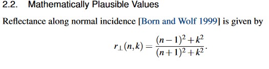
been a while that I dove into complex IoR (I built a complex IoR node setup for the spectral branch) but for the polarization, if you are assuming no polarization, the best you can do is to just take the mean of the two polarizations (basically pretending you get one polarization 50% of the time, and 50% the other)

I think the most correct you can get this stuff with RGB is to determine for Illuminant E, what the correct linear RGB values for those IOR spectra are, pushing that through the math to get your actual color, and then presumably shifting that color to the sRGB whitepoint (which is D65)
But I’d have to have a good think about whether that’s correct. It might work just fine if you go D65 right away, or you might not actually want to shift the whitepoint, since this is a reflectance spectrum and not an emission spectrum…
This stuff becomes much more straight forward if you are simply thinking about it per wavelength.

At any rate, your outcomes here look great so if you are doing something wrong, it can’t be completely wrong.

this is what I had in the spectral branch (red stuff is wavelengths / spectral data, and the sines and cosines in that node group are calculated from the normal and incoming vectors. Incoming is just part of the node setup. It’s a bunch of dot products, multiplications, and subtractions to get these four trig expressions out)

You can see I’m doing both polarizations here and just weighting them 50:50

And I also looked at just the raw colors of these reflectances, showing you what is being contributed by each:

As you can see here, RS has a more intense coloration when looking straight on whereas RP more strongly reacts towards the edges. Averaged together they give a more even result overall.
I believe the two corresponding values are roughly what’s now built into Principal v2. Presumably you’d have set the angle to 0 and whatever° Principled wants for the second input to get the closest match there

If you want more info, that post in that thread, as well as the surrounding posts, should contain quite a lot more relevant stuff.
Later down that thread I also did thin film bubbles, which was far trickier to accomplish and quite maddening at times.

2 Likes

I’ll have to make some comparisons to see if there are any differences.

I’d done this, which is a complete transcription of the Fresnel function using the same approach as refractiveindex :slight_smile: Physical Fresnel (ND K) and the French Blue - #8 by Kanerka - Blender Tests - Blender Artists Community

1 Like

Yes

Its seems correct,the Born and Wolf equation from the Guldbrandsen paper is the equation part of one polarity(s),and not the whole equation.

If you add the (p)polarity its should make no difference here since we only want the color from angle 0 as described before,because they start at the same amount of reflectance.
The question is,is squaring the equation right ?

Sure you could do the math per wavelength,but the result should be the same if you feed the equation with the same lambda values (eg .45 .55 .65 micrometer).What you describe is more related to CM and internal lighting of the renderengine.

That wasn’t me saying “you should do that”, that was me saying “I did that and it made my life easier for the spectral branch”. -Clearly in non-spectral Cycles, you can’t really do that.

That is definitely not correct: sRGB is not spectral.
It might be a decent approximation but it won’t be spot on.

What you need to do instead is convert the spectrum to a color using the color matching functions. That’s basically a weighted average over wavelengths, rather than simply assuming some arbitrary single wavelength per color channel.

for Principled v2 you kinda want two values, right? The F0 and the F_whatsitsface F85 or something, I forget, which is what you get for putting in 85° into the equations or whatever.
Unless you ignore the specular tint value and do the whole angular math yourself

Is it because you didn’t use the edge tint part g?

1 Like

Sure you can do a wavelength equation for the three primary colors.I have done a thinfilm equation based on primary lamda.

For this Principled v2 we only can put in the F0 color,and this equation is for the F0 reflectance.
What Fresnel equation is used in the shader for the metallic?

Not really. You are dealing with RGB colors, not individual wavelengths. However, doing the conversion from spectra to colors ought to give you a decently close result regardless.

No, the specular tint is the other color in question.

I forgot what exactly it was but that info should be buried somewhere in this thread. At any rate, it involves both the base color (as F0) and a second color, the specular tint (corresponding to some angle the exact value of which I forgot)