This would be possible (it would require me to change the code somewhat to keep a per-edge clamp value, rather than the global one I calculate now). One issue I foresee, though, is that if you go all the way to a clamp value then you get zero-length edges, which is not a “clean mesh”. A subsequent “remove doubles” might fix things, but no guarantee. And anyway, clamping anywhere means that there will be beveled edges that are not the bevel width the user really wants, so this isn’t really the right solution. The right solution is to actually change the geometry as the beveled edges sweep over vertices. But this is pretty hard, so I haven’t done it yet.
2 Likes
While I agree it would be better to solve it right, I have to say that I personally turn clamp off very often and honestly, in like 90% of cases the problematic spot isn’t visible (which is the reason why I turn clamp off).
Nathan’s solution would work great I think and I’m surprised I never thought about it. It’s not really about bevel width not being correct but more like bevel width being 90% correct and in the rest of cases at least not creating intersecting mesh or infinite spikes.
If remove doubles is implemented can it be made to really do it only locally on the 2 (or more) beveled vertices and not everywhere? Very often the mesh is split and some vertices share location so doing it globally might cause issues.
Writing all this and thinking about 10k meshes I fear the speed will suffer greatly…
1 Like
Thanks and it actually might not be as CPU intensive as I originally thought since each vert clamped is one less path to calculate, so potentially it could even optimize the bevel modifier. If it turned out to be the worse case scenario it would still be faster than manual, not to mention a 90% fix is typically good enough for 90% of people (especially beginners).
There would be very little effect on CPU time – essentially none – if we were to clamp per-edge.
5 Likes
Well that’s awesome, I imagine the amount of time that would save people would be huge. Though I’m sure coding something like that would also be really time consuming, but still it is fun to imagine, thanks for the info!
cgslav, I just committed a fix to this bevel modifier with hardened normals bug that you reported on Oct 9. Sorry it took so long to fix. Thanks for telling me about it!
11 Likes
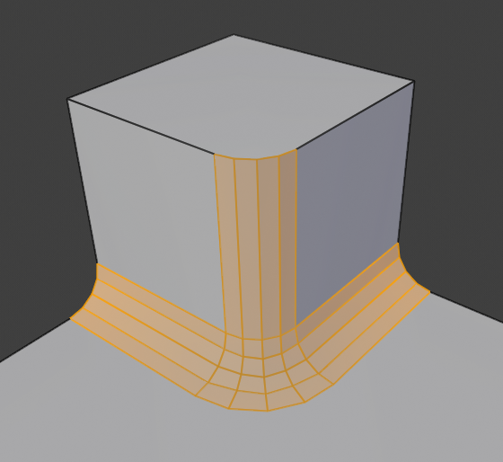
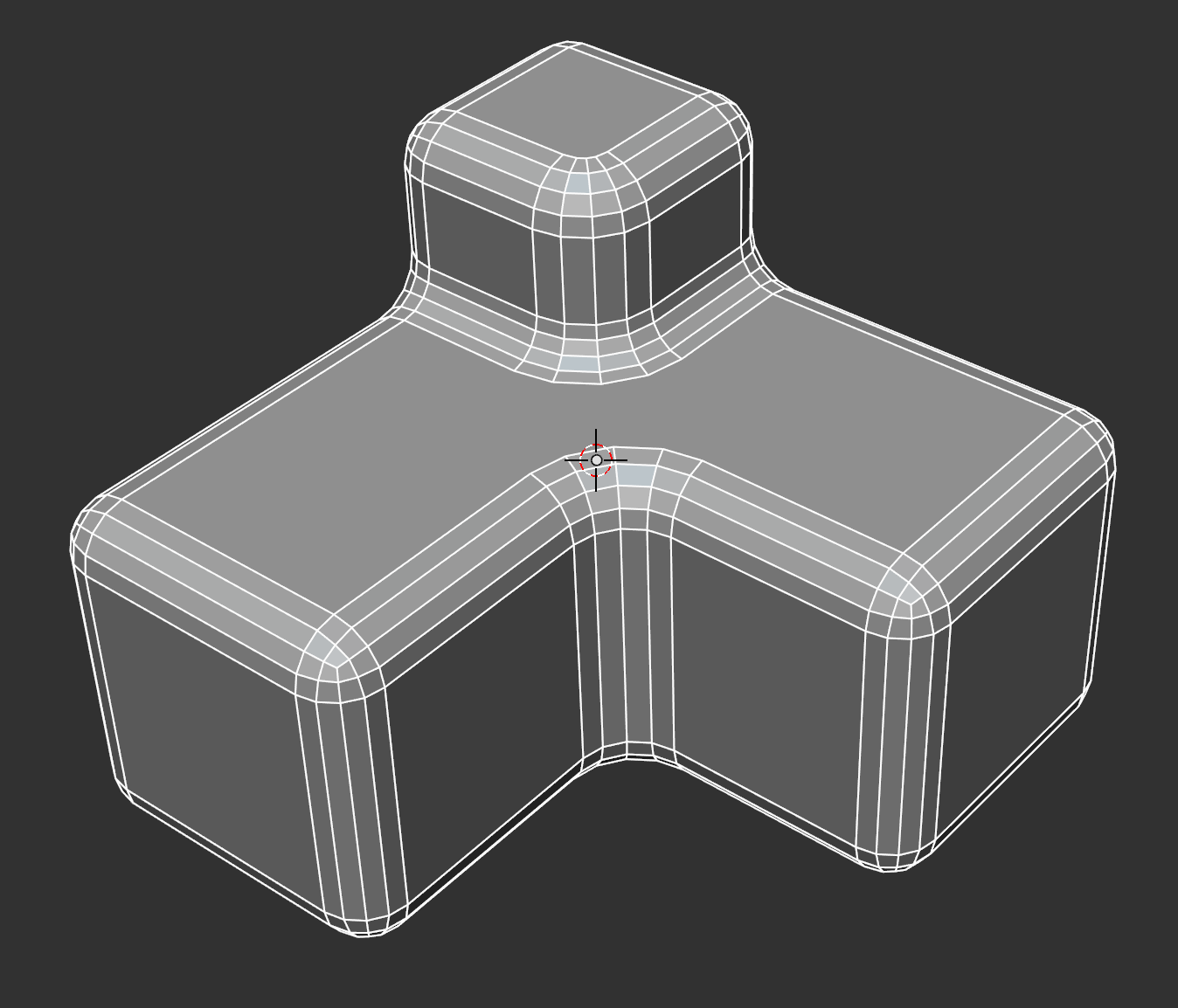
I am looking at some buggy behavior with the harden-normals mode for bevel (both the modifier and the tool) as currently implemented in 2.8. And I realize that I don’t know exactly what it should do. I’d like some user input. Consider this diagram:

Now if a user wants to “harden normals”, I believe this means that the “per-vertex-face-normals” (aka “Loop normals”) at a, b, c, d, e, f need to be set according to some rule that in general leaves the big faces like A as looking flat at the junction between those faces and the newly-created bevel geometry. But this leaves some questions about what happens elsewhere in the model.
Here’s what I think the new per-vertex-face-normals should be; in some cases, there are questions. These all assume that the normals have all been “split” so that there are custom normals for each face/vertex pair. (If this isn’t true already, the harden-normal option should cause that as a side effect, do people agree?)
a - pre-existing custom normal (probably A’s face normal, but user might have edited it – if the whole object was desired to be smoothed then it may be the vertex normal at vertex a)
b - pre-existing custom normal? or A’s face normal? or (some kind of) average normal between A and bottom face if pre-existing custom normal was the vertex normal for the original front lower cube vertex? My best guess: if pre-existing custom normal is not A’s face normal then angle-weighted average of the faces around be that are not part of the newly created geometry for edges and vertices.
c, d, e - face normal of A. (But what if original edge that created bevel face A were marked “sharp”? Should we then use D face formal for d and C face normal for E and who knows what for f?)
f - vertex normal of vertex at f (i.e., angle-weighted average of normals of face C and other 3 faces around f)? What if faces are not smooth shaded – should bevels be faceted (that is, should we be using C’s face normal)? My best guess: no.
If the answers to the above questions are clear, then there are too many options for the bevel harden normals right now (e.g., I don’t think the “face strength” and “vertex average vs face mode” of hardening are necessary, nor the “fix shading” mode that frankly I am not sure what it does. If the answers are not clear, what options should there be?
And what if the user wants to have bevel affect “Face Strength” (Weak, Medium, Strong) so that a Weighted Normal Modifier can use it later? Should that be done instead of or in addition to normal adjustments (my best guess: instead of). And would it be sufficient to just set the “Face Strength” of all of the newly created geometry for edges and vertices (highlighted in the diagram above) to get strength “Weak”, or are more options needed?
I realize that in beta we probably shouldn’t be changing much, but I think the current code and options are pretty confusing. What do other users think.
I want to look at this, but my brain’s not up to it right now. I’ve set a reminder and will get to it later, if nobody else does!
1 Like
@Howard_Trickey Great change to Bevel modifier! Thank you very much for this one.
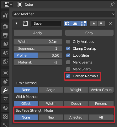
You should also consider checking AutoSmooth along Harden Normals automatically and maybe deselect it as well with it. Now user can’t see any result by clicking on new option.
2 Likes
I’ve also had a play with the new options and honestly couldn’t find anything new that actually did what I expected/anything at all.
What I imagine the most useful feature would be for a hard-surface modeller is a “flatten original faces” checkbox with different wording. This would have the following behaviour:
a, b, c, d, e (assuming c, d and e refer to the normal of the vertex joining A, B, C and D): retain A’s normal
f: in this case, be a weighted sum 1/3A + 2/3RightFaceNormal
B: not sure what I would do here… but I think it would work out that the true normal would end up equalling what I would expect to see.
C: this gets tricky. I’m not familiar enough with how face normals are generated and used to say for sure how this one would work. Are face normals not just either an average of the it’s vertices normals, or perpendicular to the plane made by the vertices (if they are coplanar)?
I’m not sure if I’ve contributed anything you wouldn’t already know, but I think I understand how I would expect the output to be.
Note that there’s also a thread on BlenderArtists where I asked the same question and got more input than here up to now. See https://blenderartists.org/t/rohans-bevel-gsoc-work-is-now-officially-in-2-8/1121995/10
Also note that after I submitted the changes, I realized that things don’t always work at all as expected if the faces are marked as smooth shaded and autosmooth is on before doing a bevel with hardening. I apologize for that and will hopefully fix soon. A scenario that I do think works pretty well, for testing now, is: take a model with all faces flat shaded and turn on autosmooth. Then do a bevel and enable ‘harden normals’. Use the overlap option to see per-vertex face normals to see the effect of hardening on the normals.
Answering the above questions/comments:
cgslav: I agree, I should automatically select autosmooth if it isn’t already checked. I want to do that in a separate commit, though, and check it well before doing it.
smilebags: I’m not sure if it is clear to you what a,b,c,d,e,f represent in my diagram: these are “loop normals” or sometimes called “per-vertex-face-normals”: each of them can be independently set to whatever we want – that is, c, e, and d can all have different loop normals.
What I have implemented now is that a, b, c get the normal they had at those corners before beveling – those are probably the same as the A face normals, if autosmooth thinks the edges involved are sharp; d and e get the same loop normal that c gets (i.e., the orignal loop normal at that corner of A before beveling). f gets the average of the face normals of the two “long edge” faces adjacent to it: B and the unlabeled long edge just to the right of B. I think this will be the same or approximately the same as your formula but with weights reversed: 2/3(A’s face normal) + 1/3(unlabled grey face pointing right-ish face normal).
1 Like
@Howard_Trickey loving the work so far, I don’t know if you are looking at profiles and this may be an old issue but are you aware of the odd bevels when using Profile = 0 and indented extrusions?
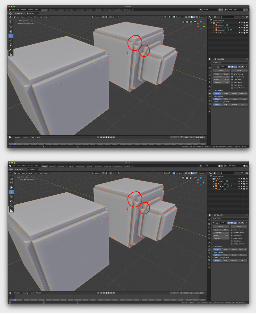
AnadinX, I’m not sure there is a good one-step solution to what you are trying to do there. I could get something that looks better by first beveling only the square loops of the insets (unselecting the connecting diagonals and short extrusion edges) and then separately beveling the short extrusion edges.
Just pinging, maybe you have some insights into this: https://developer.blender.org/T60241
Thanks!
1 Like
I have changes ready to allow different miter patterns. An example:
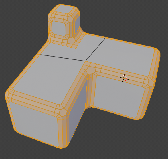
and another:
I will probably push these changes in a day or two unless people think this is too big a functionality change for a period when we are in beta (?).
46 Likes
It’s fine, we’re still a while away from final release.
2 Likes
Wazou, yes, you can get that picture with my changes. Well, almost. The one edge that won’t be achievable is the arc on the front corner of the back top face. You can get arcs like that but if enabled they have to be on all non-reflex angles, and the rest of the 90 degree angles in your picture don’t have an arc there.
Right now you can independently set the miter for (all selected) reflex corners (those with angle > 180) to either patch or arc (your picture shows arc; my first picture showed patch), and for (all selected) non-reflex corners to arc or no arc – and the width of the arc is controlled by a ‘spread’ parameter.
There is no easy way to choose subsets of vertices to get different treatment. I suppose something could be done with vertex groups or bevel weights, but I don’t want to go down that path unless there is strong demand for that.
16 Likes
A really big, big improvement Howard, thanks!
1 Like