A decimate modifier! I thought it would be a weld modifier. Nice. Thx!
But i stand by my argument: I wished we had data transfer from shaders to geometry (grey, yellow or purple noodles, but not the green ones). Not only for placing electronic parts. Imagine hair, coming out of skin pores (on a mesh with less than 1 million vertices per square mm). Or a procedural street map and buildings placed next to them. So in the end we finally could get rid of the rather disappointing texture editor and just create textures where they naturally appear: in the shader editor.
This makes more sense to me, I was actually about to propose an “attribute output” (or “value output”, or probably even better “field output”) node in the shader graph, with a dropdown to chose the type (Vector, Float or Color), and a name, just like arbitrary AOVs.
Then corresponding input node in Geometry Nodes Graph, with a material slot to specify from what material to “import” the attribute/value/field, a dropdown to pick the name of the field and a field socket output.
1 Like
Good to hear. I hope you have more success than me. I try to get noticed with this obvious evolution step since more than alf a year now, with no success.
You can use weld as well, I just used it to make the scene a bit more usable, cause performance of this build is not there yet. To really see texture well I made 300x300 grid and on 16GB of ram it’s not so fast.
No no, decimate is way superior! Great solution.
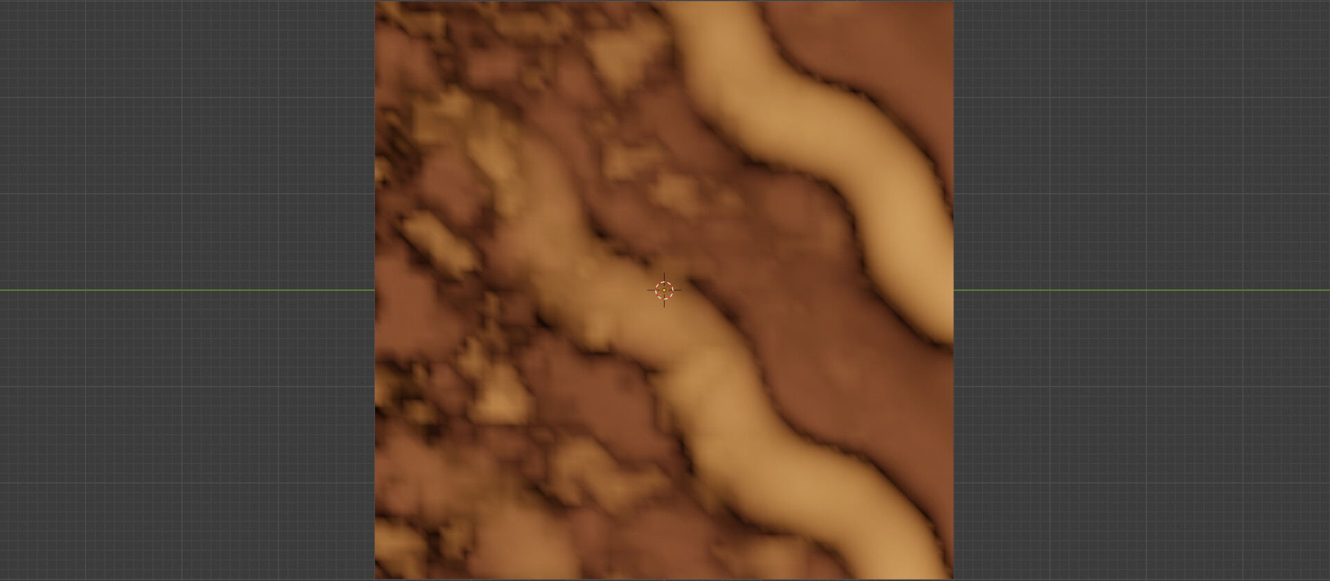
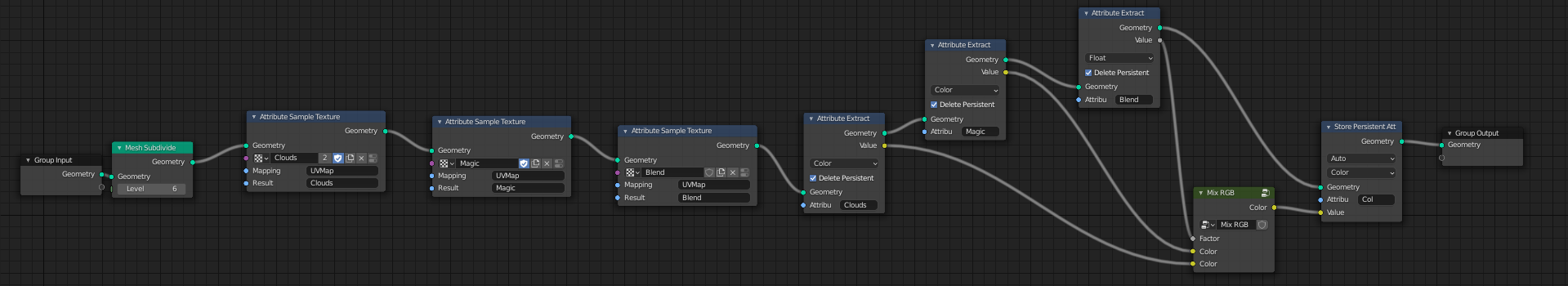
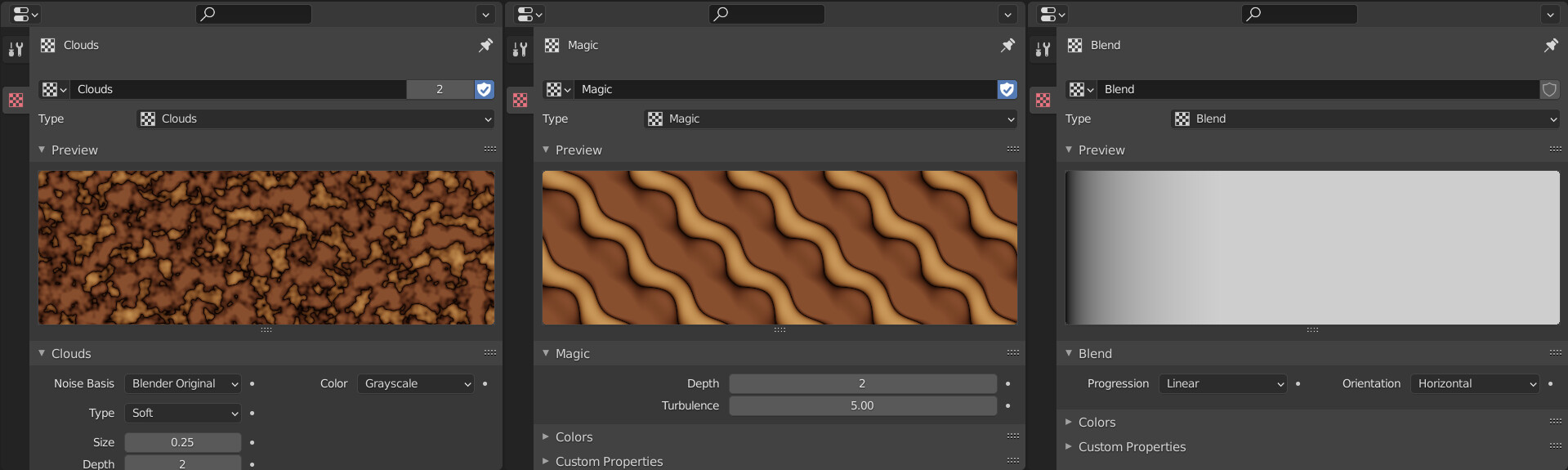
Actual color mixing is most definitely possible in fields, although the sample texture node is not updated to the new system yet, so some extra nodes are needed to extract the attribute to a field.
To start, this group will mix two floats by a factor:
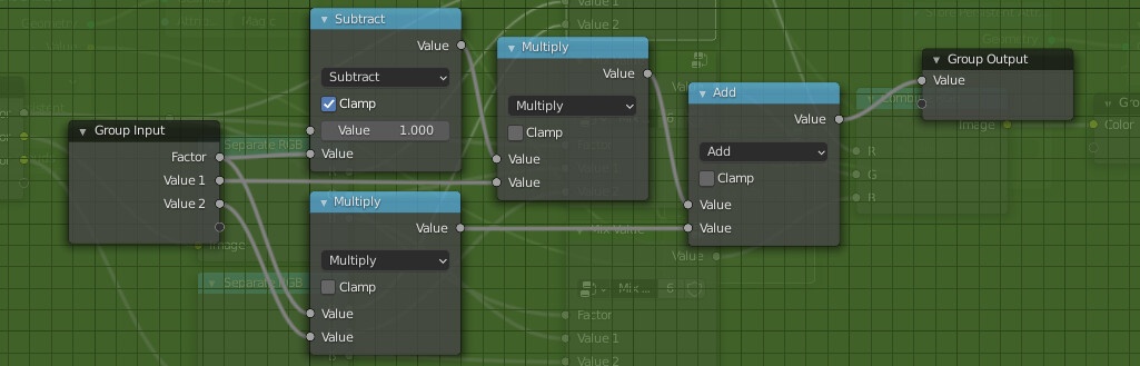
So this node will mix two colors:
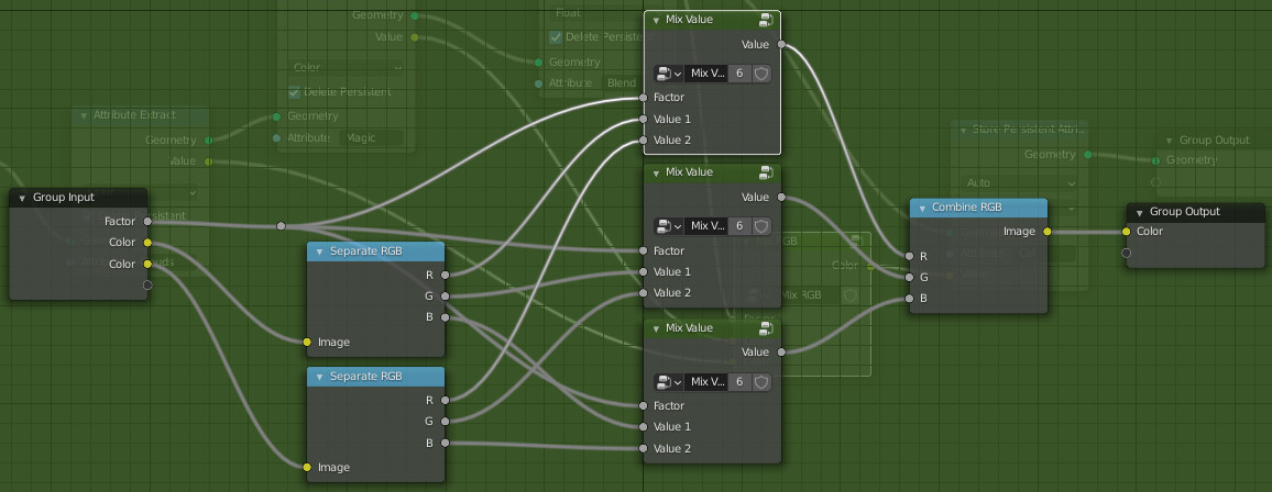
Hope this comes of use to someone.
8 Likes
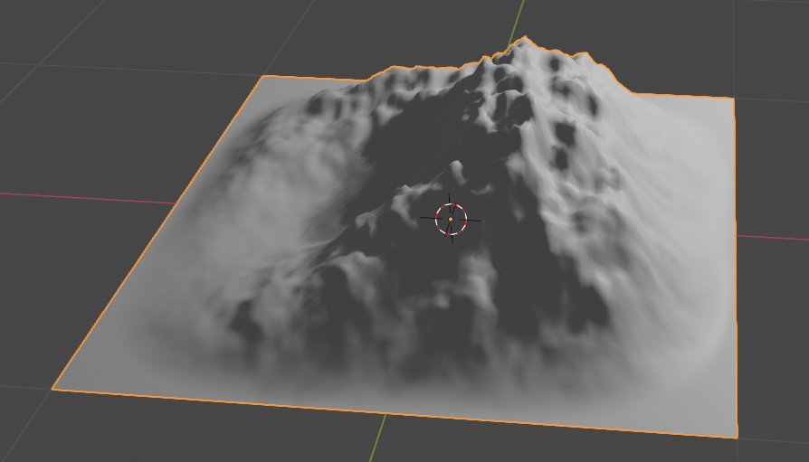
Here are another couple of selection groups: Cylinder and Tube
18 Likes
if you wanted to take a red channel and multiply it by 0.5, you could just write Color.R * 0.5. In GN, it became a frustrating affair of creating attribute separate node where you had to break vector into three individual floats, and then you had to use math node to multiply the float, and store the result in another attribute, and only then you could use it. The efficiency of these two workflows is incomparable.
Hmmm, I wouldn’t want to copy other software, but the difference in the workflow efficiency and readability is improved 1000% with the script approach. Not to mention two modes can exist perfectly well at the same time, users can use nodes and / or scripts (which can be short or long).
1 Like
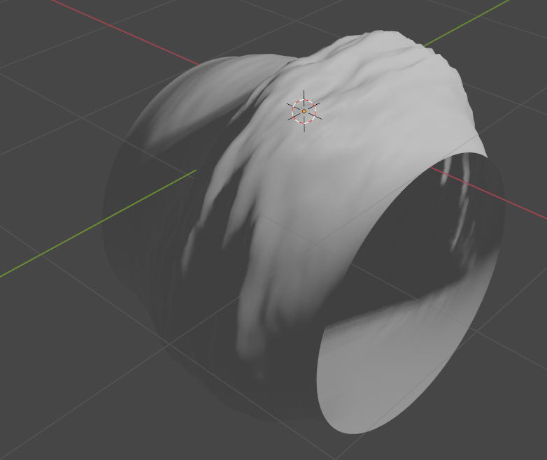
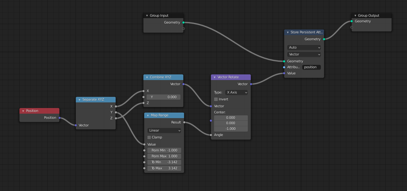
Basic modifier for warping something around a cylinder. Blender already has it, but neverless, it is fun to play with GN fields.
(1)
(2)
(3)
9 Likes
Is there a way of creating some threshold/falloff/easing on selections? For instance, if I want to use a proximity of an object to drive the distance of an extrude node with different levels of tolerance, is it possible?
Selections are boolean meaning only yes/no or 0/1 information so I don’t think so (you cant select half of polygon), but you probably can apply gradient on strength of operation which you want to make on selected polygons. It would be easier to explain on some example with screens.
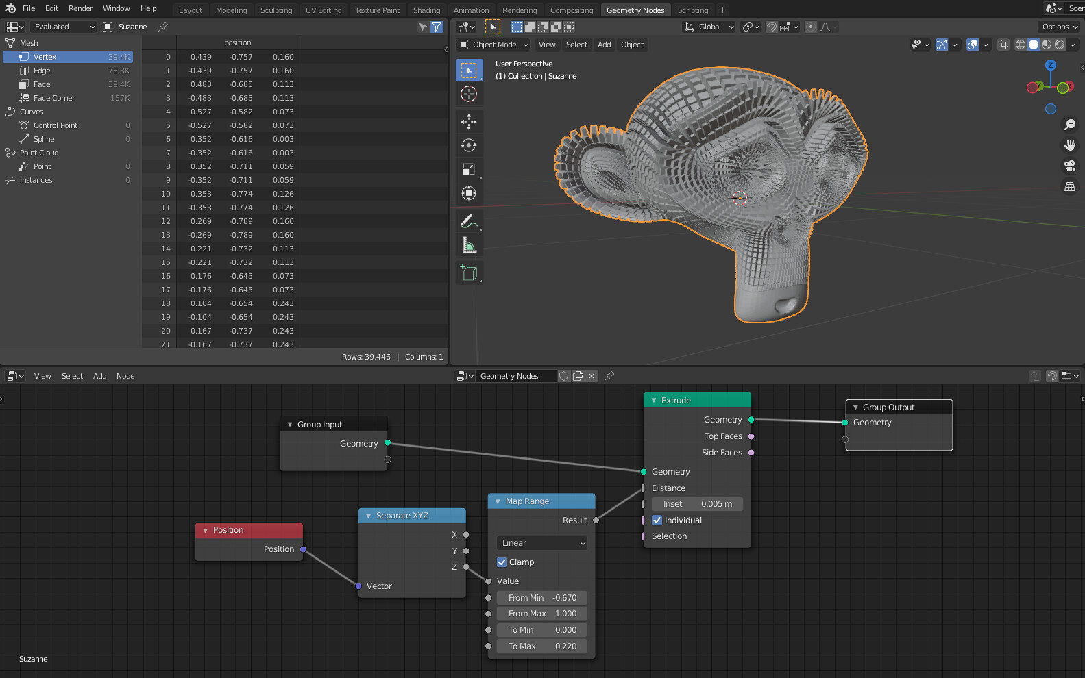
Sorry, to further explain my question, I’m driving the extrude distance using Position Z as a mask. What if I want some falloff on this control? Because right now, it acts like a boolean even though the Distance input being a float. @genesis2303
You could use the map range node directly on the Z component of position.
1 Like
That is due to your greater than node. Greater than outputs a boolean in float format. I think the math node should omit the compare operations since they are replaced by float compare node.
2 Likes
What you’re tweaking in the capture is not the distance, but the comparison operator, so you’re not getting any difference in the extrusion and that’s normal. What you should be tweaking is the Z position itself, add or subtract to it
(since “greater than” returns 0 or 1, your map range node always outputs either 0 or .150, so your extrusion depth is always 0 or .150)
1 Like
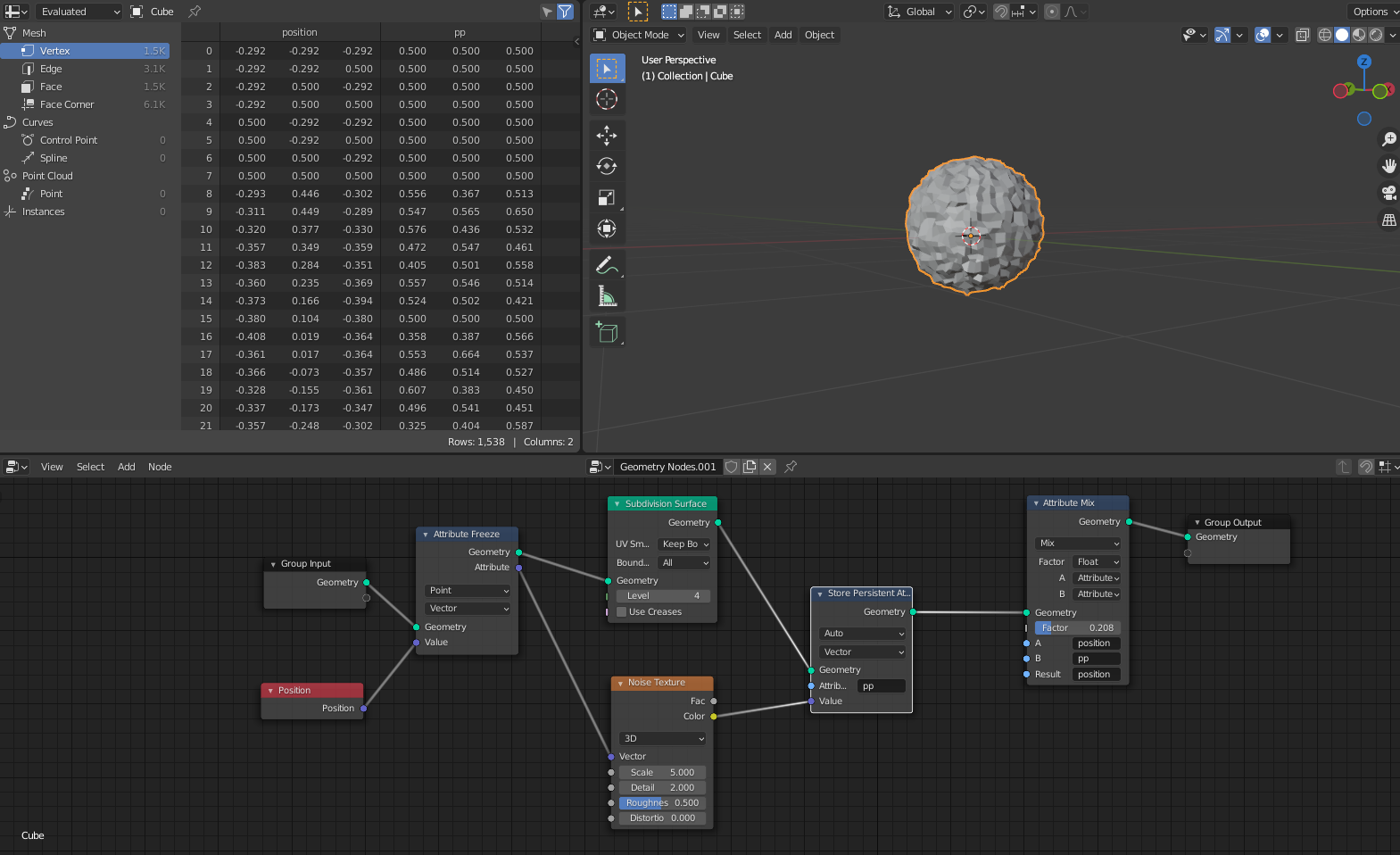
How do we use the point coordinates from the subdivision node or from the initial geometry input and mix the results with the store persistent attribute node and pass it down the stream? You can see in the video below, I can either pass the coords from the initial geometry or the subdivided geometry using the store persistent.
Basically I am hoping to use the noise coordinates of the original input and add those on top of the subdivided one as an example.
This is what @HooglyBoogly suggested
Agree, but I think that what @DimitriBastos suggested is still a nice input to further design of selections.
It would be great to have selections have “proportional editing” or “soft selection” modifier/toggle to act just like edit mode. I mean a general way of adding falloff to selections.
Since selections are booleans, I don’t see any way to implement something similar on the selection attribute itself but a couple solutions that come in my mind could be:
-
a) The select node Outputs a float “soft selection” along with the bool standard selection that can be blurred/faded, and nodes support both bool input socket selections and soft (float) input socket selections
-
b) Manage soft selections/falloffs only on input sockets on nodes on which a selection makes sense, like a transform node: It can have a boolean selection node to select what you can transform, and a falloff toggle to activate the Proportional editing, with a couple of sliders, falloff and falloff offset that controls if the selection fades inside or outside the selected area
1 Like
Thanks, that is actually pretty close to what I was looking for.
1 Like
I don’t think we need new concept for this speaking on this example I noticed kind off unexpected behavior, so till I’m using only extrusion socket everything is as expected, and with selection only also, but when I plug both selection and extrusion without changing value it goes crazy. In this kind of situation I would expect no changes. I would expect that selections would just limit extrusions to certain Z height, not give them random order, but maybe this is just a matter of demo label, or I just miss some nodes.
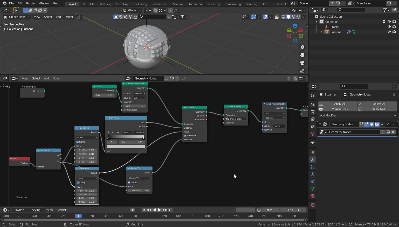
Falloffs can do those things they’re just coming in more mature stage of development, but basic ones you can make already.