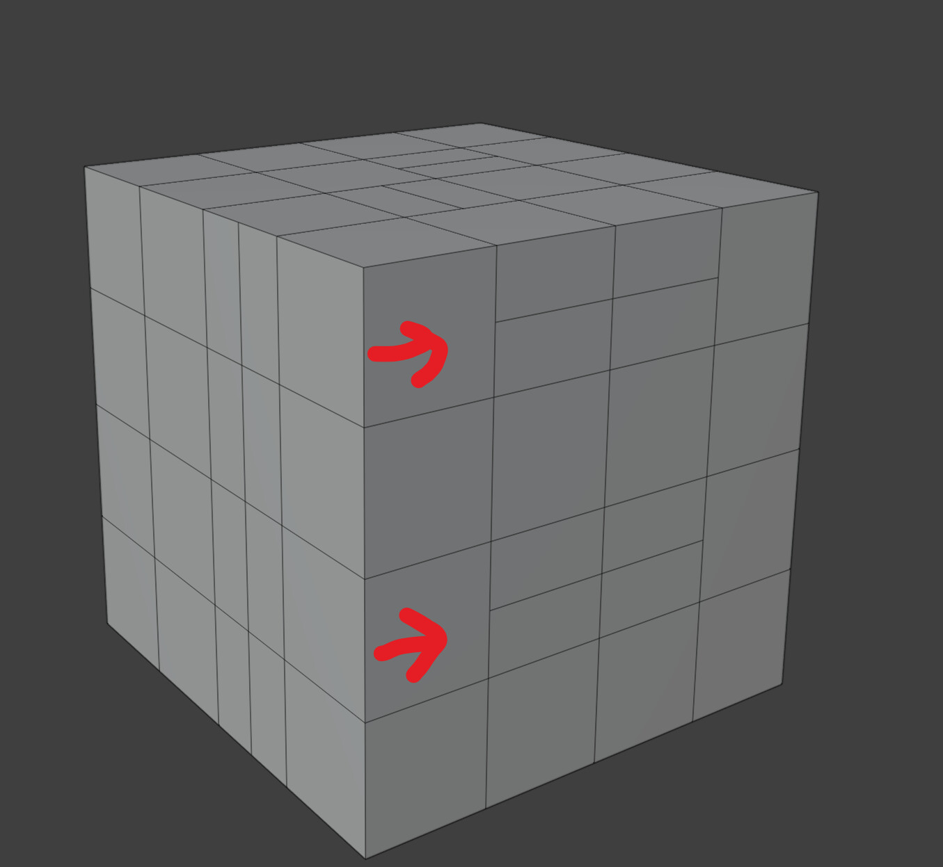
Sure, I removed it…
But you get the point… the Curves exists as an entitiy of their own- but they exist only in the 2D uv space of the Surface… I would love to see something similar in an Blender UV-editor…
Again, never saw a “real” 2d representation/visualisation of trim curves- I could imagine that it would be quite helpful (for cleaning up trim curves, visualising different trim steps/operations or general overview of involved trims) if you had a 2D view like that 
4 Likes
@ChengduLittleA there is a task page at ⚓ T94193 Curve data structures relation design that has to do with curve data structures in Blender. I do not know enough about the topic to say with confidence that it would have much effect on what you have been looking into, but if it does, maybe you can have a look.
1 Like
Thanks for mentioning! I didn’t know this specific task page before… this looks like the new curve thing that Hans is maintaining mainly. The changes in there could have some impact on how I approach the design for surface trimming, because I think I will share the curve structure there. I could take part in some discussions.
1 Like
Recent update:
Generall progress
Been messing around with curve representation. The inconsistency from all the software output is kinda concerning. This mainly cause me to think whether it’s possible to have a even “basic” modelling function in Blender for Nurbs specifically. There are too many approaches to achieve a same shape with different topology options (basically the patches are built differently), and it’s quite hard to say which is good, like whether to extrude or boolean, to blend surface or to do a sweep bridge.
Also I’m in the progress of to use the tessellation code from OpenCascade to replace Blender’s legacy one (as necessity for supporting surface trimming).
@jacqueslucke / @HooglyBoogly ? I’ve seen T94193 and the notes about curve data redesign… You guys have any specific thoughts on Surface structure? Notes seems mainly focused on spines. I will probably reuse the curve part as u/v trimming guide. I don’t think this change will substantially affect anything but just let you guys know I’m getting some attention on the surface part.
Also some problems
I’m still thinking there could be a more generic way to build surfaces robustly, just like mesh, (because what’s the point of having support of surface trimming but having no way to actually model it), but then I realized another problem, which is quite simple, you can’t really just extrude a portion of a Nurbs surface without splitting it internally, because Nurbs surface only do aXb dimensions, it does not allow branching, although implicitly we can do that with some UI tricks, however that will mess with another goal of this project which is to have good tessellation.
Proof is simple as well: Wrap around a surface so a portion of its ending side meets with the beginning side, the point count of traditional tessellation method will not match, this creates geometry problems. (Another good point of me needing to research the monte carlo remesh algorithm, which can handle this situation)
I’m also researching parametric geometry representation in general, and there’s more problems than I thought. To put it simple, it’s the same fundamental problem as when you trying to punch a perfect hole on a subsurf sphere, there isn’t really a good way to make it look good. TSpline implicitly trims and weights sub patches so you kinda get more control than Nurbs/subsurf but it doesn’t solve the fundamental problem: we are using an isotropic weighting algorithm to interpolate anisotropic geometry features.
So I’m thinking “What ability should Blender Nurbs surface really have?”, or more generically, “We seem to need a better shape control tool, does supporting Nurbs surface to a CAD-like level solve our problem? Or to what extent should we improve it?”
But at least the trimming algorithm itself doesn’t have any ambiguity  so I’ll continue working on the cascade code and update my progress here.
21 Likes
I believe that the parametric approach is very ambitious as a goal, personally I believe that the implementation of the trimmed surfaces must and their representation must be the first goal.
Then you can implement functions with snaps and the manipulation of the control vertices, and thirdly the creation of a blend of surfaces and finally the bevel of the surfaces.
Trying to make Blender a parametric CAD I don’t think is easy, it would be great just to be able to have the trimmed surfaces and the manipulation with the surface snaps.
Blender already has the basic functions for the loft, it lacks some other functions for creating surfaces from the edges, and from the network grids(Gordon), and the sweep two rail, already these are just more functions. would make Blender usable with Nurbs
1 Like
I can only offer an insight into how “a class” surface modelling is done in automotive, perhaps with you directly via Skype (or so) and than write here a brief report.
IMHo this is the most simple approach regarding complexity of resulting geometry, so could be relevant as a starting point for blender surface modelling. (Non parametric, direct, basic approach)
Edit: or you can just watch this guy’s tutorials, he has nice workflow.
YouTube Handlbar3d
I believe it’s as basic nurbs (or rather bezier) modelling as it can get.
2 Likes
Hi @ChengduLittleA ! This is quite a nice feature to have. As a insdustrial designer especially a product designer, working with CAD models with blender absolutely blow my mind! I would have shrown “RhXXX” away.
Is that anything, me as a designer, I could do to help you?
BTW, being a Chinese, I’m also in Chengdu.
2 Likes
Hi Baoyu! It’s good to know industrial designers who might be using blender to do models. It’s still a problem where there could be surface continuity requirements in Industrial Design stuff, as in G0/1/2 levels, I’d say usages like this would not likely to be satisfied in Blender because it requires a whole parametric surface builder, it’s possible but it’s not very necessary in the sense of Blender. There are a lot of user interface problems that needs to be solved before a viable design is ever gonna happen. So this thread here mainly focuses on basic curve i/o and trimming support.
你好,工业设计中若对形状连续度有较高要求的可能短期还不会做,因为需要重新写曲面的参数化描述,而这还涉及到界面表示的问题。所以这里先做基本的曲面裁剪和输入输出。我目前人在西安,还封在学校 
Glad to hear back from you. I will PM you.
This depends, if you want to build NURBS surfaces with commands like loft, sweep, etc. you could store the nodes (the modeling history) within the NURBS surface object to edit its history. But any true class A NURBS modeling won’t be able to work with nodes alone. You need to align surfaces and move CV’s manually to achieve the right look (Curvature continuity). Also, you’ll be rebuilding surfaces from new edges, align previously created surfaces, use those to create new curves, delete the old curves, etc. There is just no way to automate this with nodes, even the high-end 20k+ yearly subscription packages cannot do this.
They can only store a surface history, so you can double click on the surface and for instance change the loft’s input settings (i.e. discretely control that you need 3 U spans and 5 V spans, or change the continuity from G1 to G2).
NURBS modeling is a completely different ballpark than constraints based modeling. For NURBS modeling, you want the least amount of CV’s so you can edit the surface with ease and achieve correct continuity. For parametric modeling, you may want to have a tolerance of 0,01 mm for manufacturing, so you will automatically get more CV’s on a curve to respect the tolerance (e.g. when offsetting or ‘solidifying’ a surface).
This is not meant to discourage any developments in the NURBS aspect (I’d be happy to see improvements!!!), but more of a reminder to use the correct terminology and have the right scope/ purpose in mind. There are also advantages to constraint based modeling, each tool (NURBS vs Constraint based vs Nodes) serves a different purpose for different workflows/ design stages to achieve different goals.
So for the modeling aspect, I would advise you to be a bit more precise :).
It’s probably easier to start with just the freeform modeling without any constraints/ parametric approach. In parallel we could think about the requirements for parametric (constraints based), parametric (nodes based) or NURBS modeling (Class A) and the data structures they would require (sorry can’t help you with the latter). All these modeling packages started out, like Rhino, as freeform, no constraint modelers, that way, you at least know the math works for the modeling tools and it also takes away a lot of complexity initially.
Agreed, your phasing sounds reasonable.
P.S.1 Rhino has an Opennurbs kernel (opensource), perhaps that’s worthwile if Opencascade fails to do what you want to…?
P.S.2 T-Splines has been superseded by Opensubdiv Nurbs patches, this is what is used in Alias now and I presume also for Rhino. T-splines is an Autodesk trademark and incorporated in Fusion 360 & Inventor, but has proven too slow for NURBS modeling the way it’s done in Alias, so Alias Speedform (the T-spline Alias Spin-off) was terminated.
P.S. 3 AFAIK Blender doesn’t use double precision so being held back by single precision would severely impact what is possible in terms of tolerances anyways. @ChengduLittleA and @HooglyBoogly is it feasible for the curves data to have a double precision? Same goes for surfaces?
2 Likes
There also is the Alias Theory builder for basic concepts, Handlebar3D’s Aaron Howell’s serie shows very precisely how NURBS surfacing works, Alias tutorials by Barry Kimball may also be of interest, as well as Alias’ history visualiser (check the What’s new video’s from 2021 and 2022 from the Alias Youtube channel).
The latter may be a roughly compatible system for turning modeling work into a Geonodes equivalent. So you have the flexibility to model and build simultaneously build a node tree in the background.
Though, this is only to understand the modeling concepts and workflows, not to breach any copyright stuff.
You can store edit history as nodes as well. It doesn’t matter.
Double precision is okay afaik but how much “tolerance” do you want anyway? At least not for the control points… Intermediate/interpolated points may need higher precision but we need a use case comparison.
I’m not sure “how” tspline is slow by principle. This needs investigation.
OpenNurbs is a file io, it does not calculate surface tesselation for you.
1 Like
Since I haven’t used Alias/ ICEM in production, maybe @JLBohm has a better understanding of this. I’m just bringing it up here.
T-spline is different from your average SubD NURBS patches, because, as the name implies, it can allow for T-junctions within the SubD. And it would be perfectly fine, the model would subdivide just fine, so it doesn’t require all quads input.
I think, that the trademarked T-splines was the first implementation, or one of the first, to arrive on the market for Rhino. So what I’m saying, is OpenSubdiv NURBS patches are different from this. Because of the T-junction and the underlaying mathematical foundation, T-Splines is apparently a lot slower than the OpenSubdiv equivalent. T-splines just refers to this particular application, it is not the name you would be using to describe the technology in which you can import a mesh — or model as if it was a mesh — and convert it to a NURBS surface. The family name is SubD, T-Splines is one particular ‘brand’ within this family. Hope this makes sense.
2 Likes
@ChengduLittleA
@Hologram
In automotive design (specifically VW group area) 0.001mm position tolerances are tightest used, most of the time this is overkill. After that data are refined in other software for manufacturing, but lets not talk about that.
Typically 0.01mm position and 0.1deg angle for tangency.
Imagine 2 surfaces both with trimmed ends aligned together with tangent or curvature continuity.
Not sure for how many steps you need to measure that on the boundary.
Here we talk about various tolerances and continuities at the level of ICEM Alias etc., and other high-level concepts, it would already be enough to have the possibility of trimmed surfaces and some basic functions such as surfaces ruled gordon sweep 2 rail and blending.
Everything else seems to me impossible to happen in Blender, considering that already a good implementation requires excellent skills in programming and knowledge of Euclidean geometry, and also knowing programming well.
Yes I agree, Blender wouldn’t be used for that end anyways. Only to concept/ render, but I it’s good to keep in mind nonetheless now that curves are overhauled. I recall there being a discussion on tolerances over on the Rhino forums for G1/G2/ G3 angular deviation with slightly tighter constraints. Also, Alias has presets on this for exporting to various CAE/ Cam packages for tolerances, which could be referenced.
__
But, what would happen with a vertex’ tolerance if it were to be aligned and moved multiple times in succession? How much would the actual deviation be with single precision vs double precision? This is just me being curious.
I’m not sure how likely blender is gonna be used to do this kind of [precision] modelling. Although the step file could include tolerance info and we can tessellate the surface accordingly.
A problem is that surface projection cutting isn’t exact as well. It’s hard for any software to do it with in certain tolerance without using a large amount of control points. To my understanding, this kind of boundaries are typically manually fitted and adjusted anyway, so to my concern the control points can be handled normally just like any mesh points.
1 Like
This got me thinking - Id like to do a little brainstorming what use cases would benefit from proper nurbs integration and with what tools - to have broader context when implementing this.
@ChengduLittleA do you think there is place for this in this thread, or rather do separate topic?
3 Likes
Hi!
Sorry for the long pause…
I think yes, we can keep ideas in this thread.
Alright, here my take on what proper Nurbs’n’Curves could mean for Blender users, I hope to start a discussion here.
Every step is added on top of previous one:
- “Barebones” implementation - basically goal of ChengduLittleA right now (right?)
- Visualization for product, industrial design and various industries, architecture. Also great when polygon modeling based on Nurbs references.
- Features: Step/Iges IO, control over “background” tesselation density, handeling normals, UVs
- Nice to have: basic modification of control points, untrim/trim (ideally keeping trimming boundaries around), basic support for Geometry Nodes, at least for materials. Tesselation density based on view-distance handled bz GN would be cool
- Basic Surface modeling
- Product+industrial designers, architects, being able to model basic objects with surfaces.
- Features: Maximum possible support with existing tools for moving vertices (bend, shear, proportional editing, etc.),
tools for complex trimming/untrimming, keeping trimming boundaries around for reuse,
basic aligning tools (+ modifier/Geometry node?), at least for positional alignment.
Basic tools for surfaces creation like Extrude, bridge curves, revolve, sweep, offset, etc. - Nice to have: Maximum possible support with existing Geometry nodes
- Advanced Surface modeling
- Feature completeness, robustness and controll for most of product/industrial/automotive design modeling needs, precise freeform modeling for 3d printing, complex transitions, Generative/parametric stuff with GN
- Features: Advanced alignment tools (tangency, curvature, enough control over points flow, also on curve-mapped-on-surface, not only borders),
Creation of transitional surfaces (secondary, tertiary, like radius, cuvature blends), possibly with GN and being able to “bake” them and modify by hand,
exact extend/shorten tool, exact reconstruction of surface inside its trimming boundaries (“hard trim”)
better proportional editing workflow with exact controll over which points are influenced,
Surfaces-specific Geometry Nodes for parametric design
- Super-Duper-Sci-fi-grade modeling (I can dream right?)
- New never before seen, industries-disrupting worflows with seamless hybrid Surface-Subd modeling
- Features: both-way parametric alignment between Surfaces and Subdivisions,
Automatic conversion of Subdivisions to Nurbs patches in the background - Best of both worlds in terms of surface control and flexibility
- Cool and powerful Geometry Nodes with possibility of hand tweaks
…
Im I missing something? Do I focus too much on products modeling? Are there other industries which would benefit massively from proper Surfaces support of various complexity?
6 Likes