Add object tool, requesting feedback

The new Add Mesh tool introduced in 2.90 has some really poor UX choices, resulting in really poor usability compared to similar tools in other software. Namely, in the pursuit of some fallacious ā€œconsistencyā€, all the different shapes are created with non uniform scale, requiring press of an additional modifier key to make them uniform. This goes against general expectations of many users, where they expect certain shapes to be uniform by default, while others not.

Itā€™s a really, really bad idea to go the consistency way here, instead of going the ā€œwhat the user expects to happenā€ way. So what should happen:

  • Cube should be created non-uniformly, and require modifier key to be uniform. (Happens currently)
  • Cone should be created uniformly in XY axes, requiring modifier key to be non-uniform (Does not happen currently)
  • Cylinder should be created uniformly in XY axes, requiring modifier key to be non-uniform (Does not happen currently)
  • Spheres should be created uniformly in all 3 axes, requiring modifier key to be non-uniform and initiate 2 step creation process (Does not happen currently)

I can not stress how important it is to get this right, since during modeling, primitive creation is something that happens very often, so getting the UX wrong here will ruin the efficiency potential this tool could bring, if done right.

3 Likes

Heh Add object tool, requesting feedback

Hello there! I have mentioned some feedback regarding this tool in the bug report on developer portal: https://developer.blender.org/T78663. Wanted to make a reminder here.

IMO, the add object tool should respect orthographic mode and snap to the grid respecting the orthographic mode it is in. Currently Add object tool allows you to set primary snapping axis manually making it not really user friendly. Right now, if youā€™re in front view or side view, you create a flattened primitive that is invisible for the most part. Being able to use this tool with automatic orthographic mode grid snapping would make it so much more usable as a lot of modelers use orthographic view quite extensively.

Also please consider that a lot of users use align to view settings in the editing tab turned on, this way when you create any geometrical object it snaps to the view angle youā€™re in, it allows you to basically draw the geometry from a certain side. I think this tool should follow the same logic when using it in ortho mode.

Thank you for adding this feature in 2.90, it opens many more opportunities for further development and makes modeling even more comfortable in blender.

There is an issue in combination with the IC Keymap that is really annoying. Alt + MMB ( pan viewport ) does no longer work while the tool is active.

Oh yes! I was just thinking about that it would be really useful to have the tool maybe be useable as a way of inserting custom meshes onto the surface of other meshes. Sort of like the Insert Multimesh brush in ZBrush.

I donā€™t know if this is in the scope of the add object tool or if this is rather a sculpt feature.

Committed surface orientation, since itā€™s one of the most requested features. Iā€™ll check on other suggestions listed here next.

17 Likes

working great :slightly_smiling_face: thank you

please add plane/grid primitive

ā€¦ and maybe curve rectangle, circle and arc. :pray:

@ideasman42 add object tool is always snapping to edge even if only vertex snap turned onā€¦ if I have some mesh edge over a curve point, the point is ignored by snap systemā€¦ Iā€™m using curve lines as guide to fast draw aligned cubes, but I cant to snap curve vertex/point if it is crossing a mesh edge.

edit: vertex from other mesh objects is ignored too.
edit2: please, if you can, add mouse wheel view zoom in/out while drawing (to fine snap adjust) :pray: :slightly_smiling_face:

This tool is super cool, Iā€™m excited to see it improve. I had a few problems and possible solutions I wanted to share. Some things pertain to the discussion in the task comments: https://developer.blender.org/T57210
But I think Iā€™ll get to that stuff in another post.

First couple problems:

  • If Orientation is set to Surface and snapping is enabled, itā€™s difficult to get a good result when starting an Add Object operation from a vertex or edge.
    Because the surface orientation depends on where the cursor is at the start of the operation, and because the userā€™s cursor has to be very close to a vertex or edge for snapping to happen, it takes an unusual amount of mouse precision in order to add the object on the desired surface.
    ā€“
    Example: If, with snapping enabled, I want to create an object on the top face of this box, but my cursor is slightly on the wrong side of the edge, Iā€™ll get an unusable result. It took me a while to understand how the tool was working during these cases, even though itā€™s just being consistent with itself whether or not snapping is happening:

    Also, if the userā€™s cursor is not on the mesh at the beginning of the operation, then the created object will actually be oriented to the snapped vertex/edge normal. I have my doubts that this is useful, but I dunno:

My idea for a solution:

  • When adding an object to a surface, always use that surfaceā€™s normal (relative Z axis) as the placement plane
  • When Orientation is set to Surface and snapping is enabled, continually change the orientation to whatever surface the userā€™s cursor is currently over during the initial part of the operation (before the user releases the mouse button and drags out the height of the object), instead of only setting the orientation at the start of the operation.
    Like this:
  • If the user moves the cursor off the mesh surface during the initial part of the operation, either:
    • Stay in whatever surface orientation the userā€™s cursor was last over
    • Fallback to the first-clicked surface orientation (the default behavior)
    • Fallback to global Z orientation

What do others think of this?

6 Likes

EDIT:
Made general edits. I also realized I didnā€™t specify exactly how my proposed Orient to Surface option would work so Iā€™ve added that now.

Okay, now I want to specifically bring up the stuff @DanielBystedt, @LudvikKoutny and @DanPool were talking about in the task comments: https://developer.blender.org/T57210
I really like most of Danielā€™s proposed ideas. I love the idea for booleans and Draw on Selected, those things would really make this tool more than amazing.

However, I think that itā€™s viable to eliminate the need for most of the current tool options, which would include letting the tool automatically decide the drawing plane.
Iā€™ll show what I think the toolā€™s options can be reduced to further down. I hope I can also demonstrate that automatic plane selection isnā€™t a magical feature that would somehow guess what the user wants to do, or a feature that limits the userā€™s control, but that itā€™s actually a fairly straightforward solution to several issues of the tool, and it wouldnā€™t make any common usage of the tool more difficult.
You could think of it as a solution to some problems which has the side effect of making the tool much simpler to use.

Iā€™ll start with some problems of the tool.
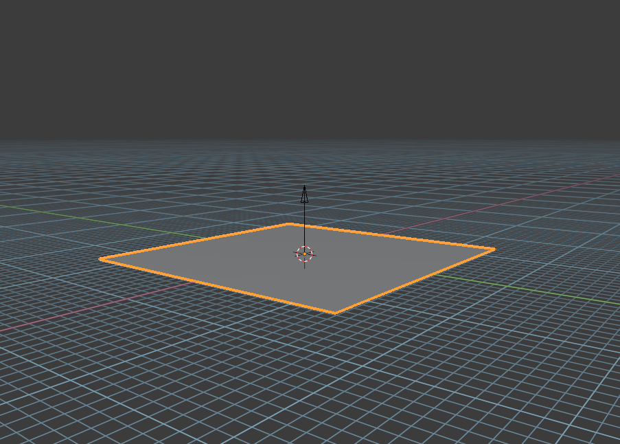
For these first examples, Depth is set to 3D Cursor Plane, and Plane Axis is set to Z. Basically this means the drawing plane is set to be the grid floor.
Iā€™ve also set the grid floor to be an opaque blue color so that itā€™s more visible.

Problems:

  • At low view angles to the drawing plane you canā€™t reasonably see the dimensions of the object youā€™re adding (except the height). It takes very little mouse movement to stretch the object several kilometers out. Controlling X and Y dimensions here requires an unreasonable amount of precision. Note the dimensions of the added object:


    I think itā€™s fair to say that the user will always orbit their view so they can better see and control the added objectā€™s dimensions. This defines one situation where it would be reasonable to change drawing plane axis automatically.
  • If the operation starts above the drawing planeā€™s horizon, the result is very difficult to control. The tool has no way to ascertain depth in this situation and chooses an arbitrary depth as a fallback. Because the fallback depth most likely contradicts the userā€™s selected Depth setting, the user canā€™t reasonably determine the dimensions and placement of the object. Remember my Depth is set to 3D Cursor Plane, but because Iā€™m making objects above the horizon, the tool cannot respect that setting:

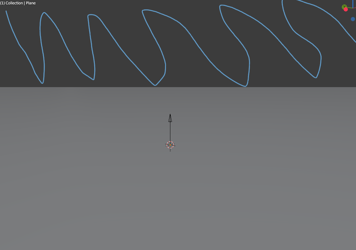
  • If, during an operation, the cursor crosses over the horizon of the drawing plane, the operation will suddenly invert, no longer following where the cursor actually is.
    In this video, I do two operations: one starting on the grid floor, and one starting up above it. Watch what happens in both cases when my cursor crosses over the horizon.

Because of these three issues, itā€™s not useful to make objects at a low view angle to the drawing plane, or above it.
In these cases, it would make sense for the tool to choose a more suitable drawing axis automatically.
This would allow the tool to more often respect the userā€™s selected Depth setting.
Automatic drawing plane selection would only affect these ā€œproblem areasā€ which are too difficult to control, actually invert the userā€™s control, or which otherwise disregard the tool settings.
Therefore automatic plane selection would not negatively impact the use cases that the tool can accomplish, it would just solve these problems and at the same time simplify the usage of the tool.

The next issue pertains more to the tool options:
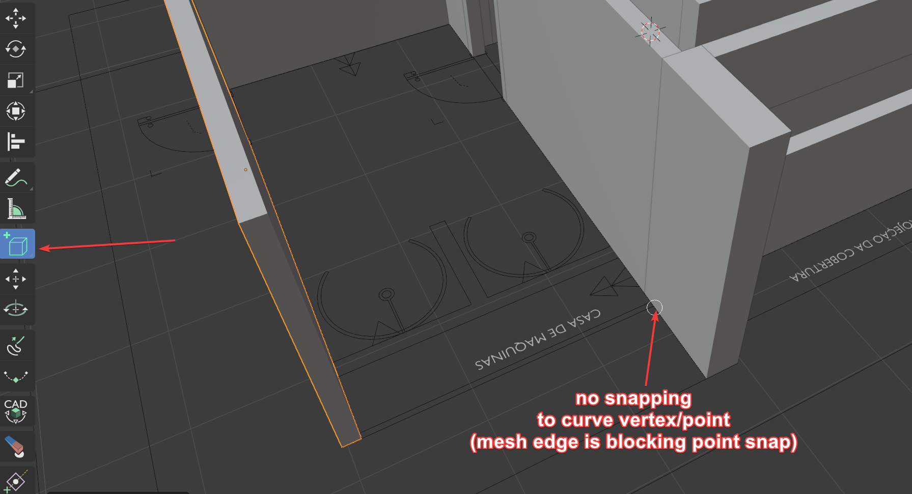
  • Itā€™s difficult to control the result when Orientation is set to Surface but the Depth to something other than Surface.
    You have to calculate in your head using the click location on the surface and the depth of the actual drawing plane in order to determine where the object will actually be made, which seems too difficult and imprecise to be useful.
    Itā€™s a bit easier to do if youā€™re facing directly at the surface that you click on. But when you do that, the height of the object is coming right at you or away from you, and then that becomes more difficult to control.
    Depth is set to 3D Cursor Plane and Orientation set to Surface:

    I donā€™t think this combination of settings is more useful than it is confusing. Especially in comparison to, say, a ā€œsurface offsetā€ setting the user could change which would place the object an arbitrary distance above or below the drawing plane. Grease Pencil has that feature, in fact. But Iā€™m not arguing for that feature hereā€¦

Related to this point, I made a mistake in a suggestion from my previous post. I said:

I retract that, because Iā€™ve realized there are common use cases in which a user might want to add an object at a surfaceā€™s depth, but not oriented to the surface. For a small example, like this:


(I made some loop cuts on the original object for easy snapping points.)
This is also a factor in how Iā€™m proposing to simplify the tool.

ā€“

Proposal / Solution:

I think that Add Objectā€™s options can be reduced down to these (considering the toolā€™s current functionality, so this isnā€™t including the features Daniel proposed):

Depth:

  • 3D Cursor
  • World Origin

ā˜ Place On Surface
ā˜ Orient to Surface

(and the origin stuff too)

ā€“

I excluded Surface from the Depth settings and added a separate toggle called ā€œPlace on Surfaceā€.
If Place on Surface is turned on, then Depth can still specify what to do when the user adds an object in empty space. That way, the user could leave Place on Surface turned on while adding objects on and off of surfaces, without having to change settings and still being in control of Depth.

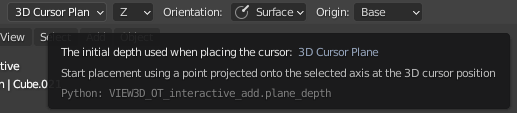
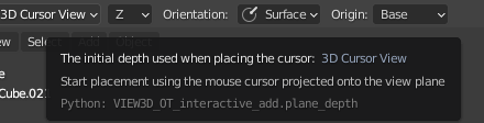
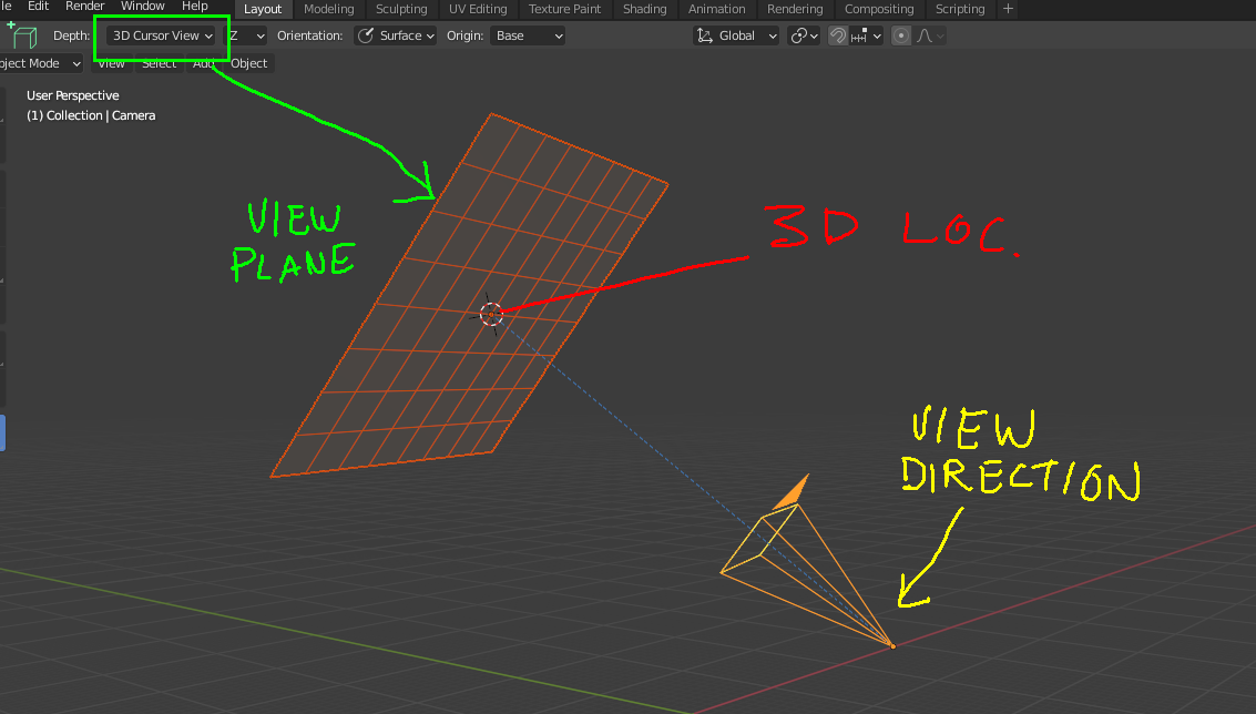
Like Daniel in his comment on the task, I excluded 3D Cursor View from Depth and added World Origin. Iā€™m personally not against the inclusion of 3D Cursor View, I just donā€™t really understand how it could be used in practice. But I donā€™t think it causes any issues either.

Most importantly, Plane Axis and Orientation are gone and the only orientation option is the Orient to Surface toggle.
If Orient to Surface is enabled, it would basically be the same as setting Orientation to Surface and Plane Axis to Z in the tool now. I also think that Orient to Surface should be grayed-out and disabled if Place on Surface is turned off. As I said before, I believe the combo of surface orientation but non-surface depth is more confusing than it is useful. This would ensure the user doesnā€™t need to disable both toggles in order to avoid this confusing behavior.

Now, what could substitute the manual selection of a drawing plane axis?
I think the first three issues I listed in this post demonstrate that whenever the horizon of the selected drawing plane is on the screen, there is a potentially very large area in the viewport where the Add Object tool doesnā€™t work in a clear and useful way.
In these cases, itā€™s not difficult to determine what plane axis would be preferable and give more useful results.
Using the userā€™s view angle and cursor location, an ideal drawing plane can be found.

ā€“

Mockups:

  1. Hereā€™s a mockup I made in Unity of the most simplistic approach, where the drawing plane is chosen based solely on how much it faces the view. In my mockups you can consider the white sphere to indicate the depth, pretend itā€™s the 3D cursor:

    Quite simply, it just ā€œactivatesā€ the plane that is most perpendicular to the view.

However, this simple approach has a problem: if each plane axis has equal precedence in the toolā€™s automatic selection, you have to look down much more than what feels natural in order to place objects on the Z axis, the ground plane. This wasnā€™t apparent to me until I started mocking-up how the automatic plane selection could work, comparing it with a couple 3D programs that have automatic plane selection with object-drawing tools. In trying to figure out why one of the programs felt much more natural and intuitive, I realized that it had a heavy bias to the Z plane.
This makes sense to me, considering gravity and all the implications that has. Itā€™s probably why Blender has a grid floor and the view orbits around the Z axis.

  1. Hereā€™s a refinement to the first mockup. It chooses the drawing plane by how much it faces the view, but itā€™s biased toward the Z plane.
    Iā€™m just sorting the planes based on an absolute dot product of the view direction and the plane axis. I just multiplied this value for the Z plane by 3 before sorting.
    Also, if the cursor goes above the horizon of the active plane, it falls back to the next best plane:

    Hereā€™s the same thing without the huge planes, just a floor and placement preview grid:

ā€“

This behavior is already quite good. In fact, I think itā€™s already good enough to replace manual orientation, and itā€™s simple too.
I think there are ways it can be improved, and Iā€™ve come up with some theories on how to do so. But as it is, this would already solve the issues Iā€™ve brought up here, and I think itā€™s the simplest and best way to solve those issues.
One thing it would need is a simple indication (and it could be very simple) of the drawing plane: Some kind of shape drawn at the userā€™s cursor (maybe a square, maybe a grid), with the plane axis color, and aligned with the plane. I think even just that would be clear enough to make automatic plane selection effortless for the user.
I think automatic plane selection like this is more than sufficient to replace manual orientation options, and would still leave the user capable of achieving all the same common use cases as with manual selection, but with greater ease and fluency.

But what does everyone else think? Did I miss some important factors?

8 Likes

Sorry for posting three times in a rowā€¦

But I thought of something that may be preferred to just a Z axis bias, and, in my mockup at least, it was no more difficult to implement.
A bias toward whatever plane is currently facing the view the most (with bias factored into this ordering).

Compare:

ā€“
No bias at all (same behavior as in my first mockup)

ā€“
Bias toward whatever plane is currently facing the view the most

By doing this, every drawing plane axis can have a greatly increased view angle range. You can see how when the Z plane is activated, I can look quite far up before it switches to the Y plane, and from there I can look far down before it switches back to Z. Note how I can rotate the view enough to see the horizon for each plane.

Itā€™s important to make the distinction here between the active plane and the plane thatā€™s facing the view the most, because there is a case when they arenā€™t the same.
Adding a bias to the active plane has the problem that if the user moves his cursor above the horizon of the active plane, and the tool activates the next best plane as a fallback, itā€™s stuck in that plane until the user rotates his view all the way back to activate the previous plane again. See here:

Adding a bias to the plane thatā€™s facing the view the most instead of whatever plane is currently active allows the use of fallback planes based on cursor position without accidentally getting locked into them:

Maybe this distinction wouldnā€™t be a factor in a different/better implementation of this, but I thought it was worth mentioning.

In these mockups, instead of multiplying the view/plane dot product by 3 for the bias Iā€™m just adding a value of 0.7.
I donā€™t know if the values for my mockup are what would be ideal in the actual tool, theyā€™re just guesses that seem good enough to demonstrate the concept.

Even with this, I think it might still be good to have a greater bias for the Z plane, lesser for the X and Y planes. Something worth experimenting with at least.

Also, this isnā€™t actually the unexplained idea for improvement I mentioned at the end of the previous post, just an idea that popped into my mind after I had posted and was going to bed.

5 Likes

I donā€™t get it. Why are you requesting feedback when you are not implementing any? The request for feedback was on May 28th, itā€™s now half a year later, and the Create Object tool is in equally as poor state as it was when originally implemented. Whatā€™s even scarier is that thereā€™s a high chance it will make it in such a poor state to the final release.

It appears that putting unpolished tools that are not behaving according to user expectation is now becoming pretty much a rule. Extrude Manifold in 2.90 and now Create Object in 2.91. Wasnā€™t the MegaGrant supposed to be used to ā€œimprove software qualityā€? I am seeing the exact opposite direction.

To be specific:

  1. The axis mode is still manual, not automatic, allowing user to select an axis inappropriate to the active view angle, resulting in very error prone object creation behavior.

  2. Most of the primitive shapes other than box are still being created with their primary dimension plane being non uniform, so it defaults to less desired behavior. The whole point of defaults in any software is to default to the most desired behavior, not the least desired one. Whatā€™s even worse in terms of UX is that the modifier key responsible for making the proportions uniform does not work when pressed prior to creation of the object, and has to be pressed only after the initial click. This is a total failure in terms of UX, specifically discoverability.

  3. UI is still unnecessarily overcomplicated for something as trivial as create object tool.

The tool feels as if it was designed by someone who hasnā€™t modeled a serious thing in their life.

1 Like

Havenā€™t read all the text but has anyone talked about Grid Snapping? you can use ctrl to snap to other meshes but doesnā€™t work with the grid/floor.

1 Like

Thanks for the feedback @justastatue :slight_smile:

======================
You wrote:

At low view angles to the drawing plane you canā€™t reasonably see the dimensions of the object youā€™re adding

You have made some comments here that it is hard to draw objects when the camera is almost aligned to the horizon. I think the general user, just like me, will intuitively understand that this is awkward and therefore draw from another view angle. You are arguing for adding an option to add an option to draw on the plane that closest aligns to the view of the camera X-Y, Y-Z, X-Z. I agree that this is a good option to add.

======================
You wrote:

Itā€™s difficult to control the result when Orientation is set to Surface but the Depth to something other than Surface. I donā€™t know when someone would want to orient an object to a surface but not also place it on that surface.

I know situations where I would want to do this, so I think itā€™s a good option to keep.

======================
You wrote:

I think that Add Objectā€™s options can be reduced down to theseā€¦
Depth:

  • 3D Cursor
  • World Origin

ā˜ Place On Surface
ā˜ Orient to Surface

(and the origin stuff too)

I have a hard time understanding exactly what you mean here. I think you mean that the depth should be to

  • 3D Cursor
  • World Origin
  • Place on surface

I agree with these depth options, but I think ā€œPlace on surfaceā€ should be renamed to ā€œSurfaceā€ for readability.

1 Like

Thanks for the feedback @justastatue :slight_smile:

You have made some really nice mockups here that shows the option of automatic alignemnt of orientation drawing plane based on the users 3d view. After looking at these videos, this is what I think

  • Adding the option of automatic alignment of orientation drawing plane is a good idea

  • This option would need a widget similair to the one at your mouse location, in order to communicate the drawing plane to the user.

  • The option ā€œBias toward whatever plane is currently facing the view the mostā€ seems to be the most benefitial option. I really liked that the plane does not switch by a 45 + 45 degree angle. As you wrote: instead every drawing plane axis can have a greatly increased view angle range

  • I do not think the plane should be biased to any axis (such as X-Y plane in one of your examples)

  • I do not think the plane should be affected by the mouse pointer location when starting to draw. Itā€™s a bit too intuitive for my taste

  • I think we still need the static drawing planes (X-Y, Y-Z, X-Z). I understand that some users think these options clutter the interface. For that reason I think we should group them and put them at the bottom of the drop down menu. I do not think the reason for thinking that they are cluttering the interface is a good reason enough to remove them, since they are only visible when you pull up the drop down menu.

1 Like

Thanks for your thoughts, @DanielBystedt! And thank you for including my mockup in your feedback on the tool.
I appreciate it.

ā€“

Exactly.
But if automatic plane selection was implemented, I think manual orientation options would be unnecessary and provide no extra benefit to the user.

We know thereā€™s a large range of view angles where the tool isnā€™t useful.
As you say, the user will always rotate their view to a better angle.
If we know there are view angles where the tool does badly, and we know what drawing plane would be better for a given view angle, then automatically choosing the drawing plane would simply eliminate situations where the tool doesnā€™t work well anyway.

ā€“

I shouldnā€™t have said it that way, because I do know situations when someone would want to do this.

But in my experimentation I felt this combination of options was too imprecise to be useful.
To me, it seems much easier to just place an object on a surface, then move it somewhere else manually, than to use those options.

Could you give an example of where the tool can more easily solve such a task, than doing it manually?

ā€“

Sorry, I think my wording might have been confusing here.

Iā€™m saying that ā€œSurfaceā€ should be removed from the ā€œDepthā€ menu and instead made into its own separate toggle called ā€œPlace on Surfaceā€.

My reasoning is this:
Thereā€™s a problem when Surface is an option under Depth.
If the user sets the Depth option to Surface, the user is still able to add objects into empty space, in other words, not on surfaces.
Thereā€™s no surface in this case, so how does the tool choose the depth at which to place objects?
Well, right now, the tool chooses arbitrarily. The user has no control over it.

The purpose of making ā€œSurfaceā€ into a separate ā€œPlace on Surfaceā€ toggle is so that the user always can control the Depth.
This would mean the user could leave ā€œPlace on Surfaceā€ turned on most of time, and still specify the Depth for placing objects in empty space.
This would eliminate the situation where the tool arbitrarily chooses the Depth for the user, and also make it so the user doesnā€™t have to change tool options as much.

Does that make more sense?

ā€“

What should happen instead when the user begins an operation above the horizon of the drawing plane? As it is now, the tool makes a seemingly arbitrary choice of positioning (as demonstrated here):

What do you prefer in this case:

  • The tool makes an arbitrary choice of object positioning (the toolā€™s current behavior)
  • The tool automatically changes drawing plane, eliminating guesswork from the tool and the user

Isnā€™t the first option more problematic?
This behavior provides no useful results, so why not instead switch the drawing plane in this situation, which would eliminate this issue?
In my opinion, automatic drawing plane selection is not really a ā€œfeatureā€ or an idea for an option, itā€™s the best solution to these problems.

Or is there a different solution Iā€™ve missed?

ā€“

I personally donā€™t think theyā€™re cluttering the interface, I just think that automatic drawing plane selection would make those options redundant.
But I suppose that if automatic plane selection were implemented as an option, that would speak for itself, and the users could decide.

ā€“

Thanks again, Iā€™m kind of scatterbrained, so Iā€™m glad to try to make my thoughts on this clearer to others.

1 Like

I think that you perhaps do not understand the meaning of the current depth options. The position of the added objects are not arbitrary, but follow the rules of the depth settings. It has nothing to do with if you view is above/below horizon. You can read the explanation of each depth option when you hover over the menu with the mouse pointer.

3D cursor plane
image

3D cursor view
image

I totally agree. I think the automatic drawing plane would cover most use cases, except for a few.

No worries :slight_smile:

Thank you but I do understand.
It does have to do with the horizon. The drawing plane does not extend above the horizon. This is just how perspective works.

Itā€™s exactly as you show:

If you extend this plane out infinitely, there is a large area of the screen that is not on the drawing plane:

When the user uses the tool above the horizon, the tool does not respect the userā€™s selected Depth, because how could it?

In this situation, the user is adding an object on part of the screen where the drawing plane, as specified by the Depth and Plane Axis settings, does not exist.
Therefore, this is a situation where the tool cannot ascertain a depth based on the user-chosen tool settings.
Because the tool cannot ascertain a depth based on the drawing plane, it instead places the object at an arbitrary depth.

This is not an opinion or a misunderstanding of the tool settings. This is a fallback mechanism that Campbell has explicitly programmed into the tool, and he can attest to that himself.

Iā€™ll try to demonstrate this again.
In this video, Depth is set to 3D Cursor Plane and Plane Axis to Z.
The first objects I add, since they are on the drawing plane, all have correct positioning.
But watch when I add objects above the horizon.
Their positioning does not relate at all to the 3D Cursor Plane:

Can you tell me how the placement of the last objects in this video is related to my selected Depth, the 3D Cursor Plane? Itā€™s not.

Hereā€™s another example.
In this video, the first 3 objects are added on the drawing plane, yielding expected results. The last object is added above the horizon of the drawing plane. As soon as the userā€™s cursor goes above the horizon, the tool selects depth arbitrarily:

Yes itā€™s correct that the object gets placed on a ā€œfallbackā€ position, when the mouse pointer is not hovering over the intended plane set in the depth settings such as 3D Cursor plane or Surface when drawing starts.

Adding the object on a ā€œfallback planeā€ in these cases feels like the least disruptive and most natural thing to do. Generating an error message is the only alternative to adding the object when the position is outside of what is specified in the depth setting. I do not think Blender should generate an error message. The current solution is what feels best to me.

No, generating an error message is not the only alternative.

My posts have been entirely about describing the better alternative.

My whole argument is that the current fallbacks and combinations of tool settings very easily produce unusable results, and that there is a simple solution to these problems.
There is a much better and robust fallback mechanism to consider, which is to automatically select a better drawing plane axis.
I am proposing it as a solution to these problems.

Automatic plane selection would almost completely eliminate these issues from the tool, make the tool simpler and allow the user to accomplish all the same use cases more easily.

You said:

But you agree now that the tool already affects the drawing plane by mouse pointer location.
So again, I ask, how is using an arbitrary depth not more problematic than choosing a clearly better axis-aligned drawing plane that would respect the Depth setting the user has chosen?

With automatic plane selection, the tool would always use the Depth setting. The tool would not need to set an arbitrary Depth, as it does now, except under very rare conditions.

2 Likes